Installation
Instructions for installing and setting up an IMS Whisper® Loader Vacuum-Conveying System: Whisper® Loaders should
not be connected to extension cords as this may cause the circuit-breaker to trip due to voltage drop. Desired mounting
surface (i.e. extruder, molding machine feed-screw inlet, hopper or day-bin) must be horizontal, flat (warp-free) and free
from debris. Ensure surface is mechanically sound and able to rigidly support the Whisper® Loader; bolt in place at the
Mounting Flange. For your convenience a Flange mounting-template drawing is included. IMS offers an array of Hopper
Covers to provide a custom fit on your material hoppers and other containers.
The receiving hopper should be vented to prevent pressurization. When properly mounted the Discharge Flapper (Dump
Valve) MUST be slightly open with an approximate gap of ¼” at the lower-most point (when system is not in vacuum
mode). The counterweight on the Dump Valve pivot arm is factory adjusted and should require no further adjustment.
Care should be taken to ensure the Dump Valve mechanism is working properly and able to swing freely to a full-open
(flap vertical) position. Remedy any mechanical interference prior to placing Whisper® Loader into service.
For Proximity Switch sensitivity adjustments and/or mounting instructions refer to applicable attachment(s) included with
this manual.
On Whisper® Loaders (PLVP, PL & VP Models) with Vibra-Pulse™ (VP) option it is necessary to connect a dedicated, fil-
tered, compressed-air supply line (see table for sizes) to the air INLET fitting on the VP Solenoid.
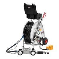
Next, make the material-conveying line connections by attaching one end of the provided Flex Hose to the Loader’s
Material Inlet and the other end to the Pick-up Lance’s inner probe; secure using Hose Clamps provided. To reduce or
eliminate static build-up within the conveying line and/or conveyed material attach the Flex Hose’s integral Ground Wire
to the Probe & Loader. Expose a short length of the wire at each hose-end, tuck inside of hose prior to connection.
Routing of the Flex Hose should be as direct and straight as possible. Avoid tight-radius bends or kinking Flex Hose as
this will impede flow resulting in sluggish system performance.
Now place the Pick-Up Lance into material source. Do not allow material level to be higher than the upper end of the
Outer Tube as material will enter causing poor flow – even blockage.
For installations where the conveying distance is greater than 10 feet, longer hose lengths or rigid metallic tubing may be
required. IMS recommends Aluminum tubing for its light-weight characteristics, ease of handling and inherent corrosion-
resistant qualities. For conveying of abrasive materials carbon steel or stainless steel bends may be incorporated into the
conveying line run.
Metallic tube bends/sweeps should have a centerline radius (twelve time tube outside diameter) on the material-
conveying line. Material-conveying lines to be configured having predominately horizontal or vertical straight runs with a
minimum number of bends to prevent “plugging” of the material. Please contact our Parts Department for assistance in
selecting proper Bends, Sweeps and Couplings. Certain materials being conveyed may require conveying lines of either
carbon steel for its ruggedness, or stainless steel to meet food-grade and/or clean room requirements. Compression-type
Couplings with 3-Bolt or 4-Bolt Clamps are best suited for metallic-tube connections, please refer to Compression-
Coupling section for additional information. Periodic inspection of the conveying line hose & tube, its condition and rout-
ing should be incorporated into the system’s regular maintenance program.
© Copyright 2007 IMS Company. All rights reserved. An ISO 9001:2000 Registered Quality Company
15
Loader Model Line Size Pressure Required
WL1250PLVP & VP Models (without Pulse Bottles) 3/8” 60-80psi
All other PLVP/PLZ & VP Model series (with Pulse Bottles) 1/4” 40-60psi