© Copyright 2007 IMS Company. All rights reserved. An ISO 9001:2000 Registered Quality Company
16
Rotate the screw clockwise to increase the time. Rotate the screw counterclockwise to decrease the time.
The screw labeled T1 = Run Timer (Default 10 seconds). The screw labeled T2 = Dump Timer (Default 3 seconds).
the panel contains two blue timing adjustment screws.
4. Timer Instructions: To adjust either of the two timers, a small flathead screwdriver is required. The timing relay within
underneath the loader is full and material is keeping the dump valve open.
3. The loader will then dump material before starting the cycle over again. The cycle will only stop if the hopper
instantly begin filling for the duration of the run timer.
2. If the dump valve is closed, the proximity switch will send a 120 volt signal to the timer relay and the vacuum motor will
turned on, the light switch will illuminate to let the user know that there is power running to the internal components.
1. The Relay timer panel consists of an On/Off switch at the front of the panel along with a “Run” light. When the panel is
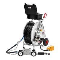
For Loader Model 1250B:
maintenance/check routine.
maintenance records in case you need to reset factory settings. Incorporate these findings into a regularly scheduled
mentioned in this manual. Make notations of these adjustments on the note page (contained herein) or in your
in the system’s overall conveying efficiency. Therefore, it may be necessary to make further adjustments outside of those
NOTE: Material density, moisture content and its flow characteristics (as well as other environmental factors) play a part
will cycle
ON
and
OFF
automatically to maintain level in the receiving hopper.
5. After the signal, the Loader’s RUN-Time starts producing vacuum and restarts sequence steps 1 thru 4. The Loader
signals the Control Panel.
low enough to allow the Dump Valve to close. The Proximity Switch senses the return of the pivot arm which in-turn
4. If the Dump Valve is held open by material in the receiving hopper, the Loader will continue idling until material falls
Filter(s) knocking particles safely away.
energize the
VP
Solenoid opening (T4 – Duration between Pulses) the Valve producing micro-blasts of air directed at the
3. For
VP
Loaders (VP,
PL
&
PLVP
models) the Motor idles in the
OFF
time mode, the Loader Control will automatically
into the receiving hopper.
2. The Loader will idle for the programmed
OFF
time (T3 - Off delay), allowing all material in the Loader to discharge
achieved, the Loader will idle as described in Step 2.
conveyed (the Regrind/Product 2 indicator light is illuminated during this time). Once the total conveying time (T2) is
prescribed time (T1), the Valve will close and then the Regrind/Product 2 Inlet valve will open allowing its’ material to be
conveyed (the Control Panel’s Virgin/Product 1 indicator will be illuminated). After conveying the Virgin/Product 1 for
Virgin/Product 1 or Regrind/Product 2 material. Virgin/Product 1 proportioning valve will open to allow material to be
1.1
PLVP
Whisper® Loaders
have two ratio-controlled (proportioning) Material Inlets to draw from either of two sources:
amount of time (T1). While the motor is running, the
CONVEY
light is
ON.
the Dump Valve is allowed to close initiating signal to convey material, turning on the motor/turbine for the programmed
empty,
1. When the Control Panel Power Switch is in the
ON
position, the
POWER
light is on. If the Receiving Hopper is
The following is the sequence of operation for Self-contained Vacuum
Whisper® Loaders:
Sequence of Operation