99903514:TELESCOPIC CRANE: 4-5
SECTION 4: INSTALLATION
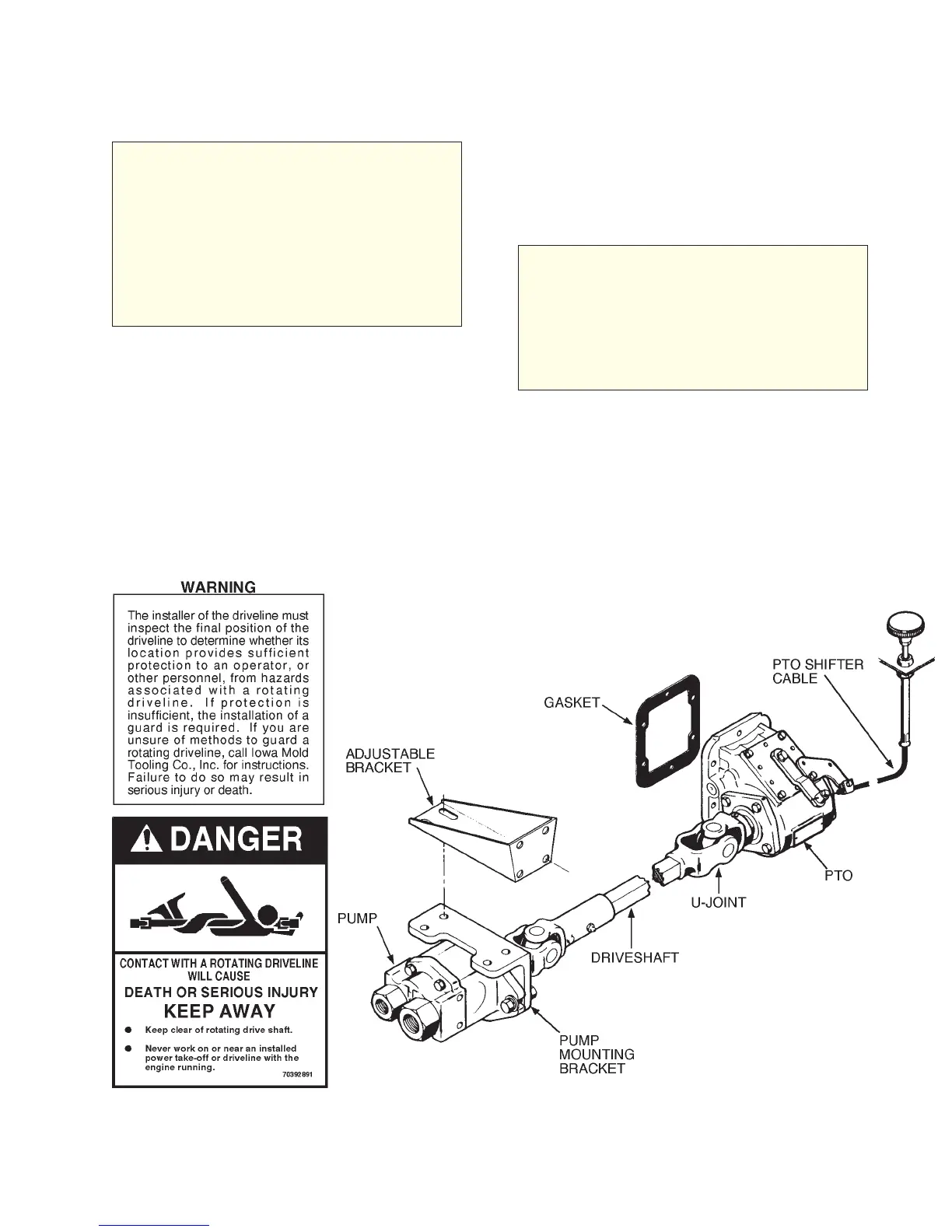
Driveshaft installation guidelines:
WARNING
DRIVESHAFTS ARE DANGEROUS!
PLACE DRIVESHAFT IN AN UNEX-
POSED OR SHIELDED POSITION TO
HELP PREVENT ACCIDENTAL EN-
TANGLEMENT. FABRICATION OF A
SHIELD OR FENCE TO ISOLATE RO-
TATING DRIVESHAFTS WILL HELP
PREVENT PERSONAL INJURY OR
DEATH.
1. Install the PTO per manufacturer’s in-
structions.
2. Loosely bolt the pump mounting bracket to
the adjustable bracket.
3. Bolt the adjustable bracket to the truck
frame at a point not exceeding 48" (121.9cm)
from PTO and where it will not produce a joint
angle greater than that recommended by the
manufacturer.
4. Check pump rotation and install pump,
pumpend yoke and PTO end yoke.
5. If a setscrew protrudes above end yoke
hub, replace it with a recessed allen-head set
screw.
WARNING
A PROTRUDING SET SCREW OR
OTHER HARDWARE IS HAZARDOUS
TO PERSONNEL. WHEN THE
DRIVESHAFT IS SPINNING, IT PRO-
VIDES A HOOK TO SNAG CLOTHING,
SKIN AND HAIR, RESULTING IN PER-
SONAL INJURY OR DEATH.
6. Size, cut and weld the driveline per
manufacturer’s instructions.
7. Install driveline and lock set screws,
torqueing all fasteners as recommended.
8. Lubricate driveshaft per manufacurer’s
recommendations.
Figure D-4: Driveline Application
20030115