EasyManua.ls Logo

Infineon AURIX TC 4 Series - Connector Pin Assignment; Pinout of X1 and X2 Connectors

Infineon AURIX TC 4 Series
27 pages
To Next Page IconTo Next Page
To Previous Page IconTo Previous Page
Loading...
Board Users Manual 15 of 27 Revision V1.1
2021-09-21
User Manual AURIX™ TCxx4 lite Kit
AURIX™ TCxx4 lite Kit
4 Connector Pin Assignment
4.1 Pinout of X1 and X2 connectors
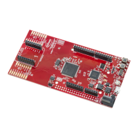
The pin headers X1 and X2 can be used to extend the evaluation board or to perform measurements on the
AURIX TC3X4/TC2X4. Figure 5 shows the available GPIOs / signals at these pin headers. The pin table is also
printed onto the bottom side of the PCB.
Pin Header X1
Pin Header X2
GND
1
2
+3V3
GND
1
2
VDD_USB
P33.11
3
4
P33.12
P00.0
3
4
P00.1
N.C.
1)
5
6
N.C.
1)
P00.2
5
6
P00.3
P23.1
7
8
N.C.
1)
LED2
P00.6
7
8
P00.5
LED1
N.C.
1)
9
10
N.C.
1)
P00.8
9
10
P00.7
Button1
N.C.
1)
11
12
N.C.
1)
N.C.
1)
11
12
P00.9
P22.1
13
14
P22.0
P00.12
13
14
N.C.
1)
P22.4
1)
15
16
P22.2
VAREF
15
16
AN15
1)
RST_S2G1
1)
P21.2
17
18
P22.3
AN14
1)
17
18
AN13
1)
P21.4
19
20
P21.3
RST_S2G2
1)
AN12
1)
19
20
AN7
SPICLK_S2G
P20.11
1)
21
22
P21.5
AN6
21
22
AN5
TXD_S2G2
P20.0
23
24
P11.8
1)
AN4
23
24
AN3
RXD_S2G2
P20.3
25
26
/ESR1
ESR1
AN2
25
26
AN1
ESR0
/ESR0
27
28
P20.14
MOSI_S2G
Potentiometer
AN0
27
28
P33.0
INT_S2G2
1)
P15.5
29
30
/PORST
Reset
P33.1
29
30
P33.2
INT_MB
1)
P15.4
31
32
P11.12
P33.3
31
32
P33.4
P11.11
33
34
P11.10
P33.5
33
34
P33.6
P11.9
35
36
P11.6
P33.7
35
36
P33.8
RXD_S2G1
PWM_S2G2
1)
P11.3
37
38
P11.2
PWM_S2G1
1)
TXD_S2G1
P33.9
37
38
P33.10
VDD_USB
39
40
GND
+3V3
39
40
GND
Figure 5 Signal mapping of the pin headers X1 and X2
Note:
1)
Different signal compared with AURIX™ lite Kit V2

Related product manuals