EasyManua.ls Logo

Infineon AURIX TC 4 Series - Hardware Description

Infineon AURIX TC 4 Series
27 pages
To Next Page IconTo Next Page
To Previous Page IconTo Previous Page
Loading...
Board Users Manual 7 of 27 Revision V1.1
2021-09-21
User Manual AURIX™ TCxx4 lite Kit
AURIX™ TCxx4 lite Kit
2 Hardware Description
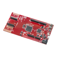
The following chapters give a detailed description of the board hardware and how it can be used. The different
parts of the kit series are shown in Figure 2 and 3.
mikroBUS
Connector
Pin Connector X2
Arduino Connector
(Digital)
Infineon
AURIX TC3X4/TC2X4
32-Bit Single-Core
Micro USB
(USB3.0 recommended)
20 MHz Crystal
for AURIX
Pin Connector X1
Voltage Regulator
5V
Infineon
Shield2Go Slot 2
Arduino Pin Connector
(POWER & ANALOG IN)
Potentiometer (10 kOhm)
and solderable
0 Ohm resistor
(R33 in 0805 imperial)
Infineon
On Board miniWiggler
10-pin DAP
Connector
Reset Button
Button 1
P00.7
LED2 (green)
P00.6 (low-active)
LED1 (green)
P00.5 (low-active)
LED3 for ESR0 Signal
(low-active)
Infineon
CAN Transceiver
TLE9251VSJ
& CAN Connector
Voltage Regulator
3,3V
LEDs D1/D2 for
ADBUS7/4
Power LED (+3V3)
Infineon
Shield2Go Slot 1
Figure 2 AURIX™ TCxx4 lite Kit Board View from the Top
Pin Connector X2
Pin Connector X1
Optional F-RAM
Optional semper (secure) flash
Figure 3 AURIX™ TCxx4 lite Kit Board View from the Bottom

Related product manuals