EasyManua.ls Logo

Infineon SAK-TC375TP-96F300W AA - User Push Buttons, User LEDs and Potentiometer

Infineon SAK-TC375TP-96F300W AA
27 pages
To Next Page IconTo Next Page
To Previous Page IconTo Previous Page
Loading...
AURIX lite Kit V2
Hardware Description
Board Users Manual 10 Revision October, 2020
LDO
Infineon
IFX27001TFV33
Pin Connector X2
Pin Connector X1
X303 X304
X301Arduino Power Connector X302
Micro
USB
S2Go Slots
S2G1/S2G2
mikroBusä
VDD_USB
+5V
VEXT
+3V3
VDD_USB
3V3
3V3
5V
5V
G1
X4
R27/0R
D5
Aurixä
TC3X5 or TC2X5
Microcontroller
On Board
miniWiggler
Potentiometer
CAN Tranceiver
Optional
External F-RAM
U1 - U5
IC1
U6
R32
U7
+3V3
VDD_USB
Out
In
+3V3
DAP
Con.
D1
LDO
Infineon
IFX27001TFV50
R39/0R_opt
G2
DC
plug
VIN
+3V3
+5VVIN
Optional
External Flash
U10
U11
VEXT
Out
In
+3V3
I2C Eeprom
U9
10M / 100M
Ethernet
U8
D2 X3
+5V
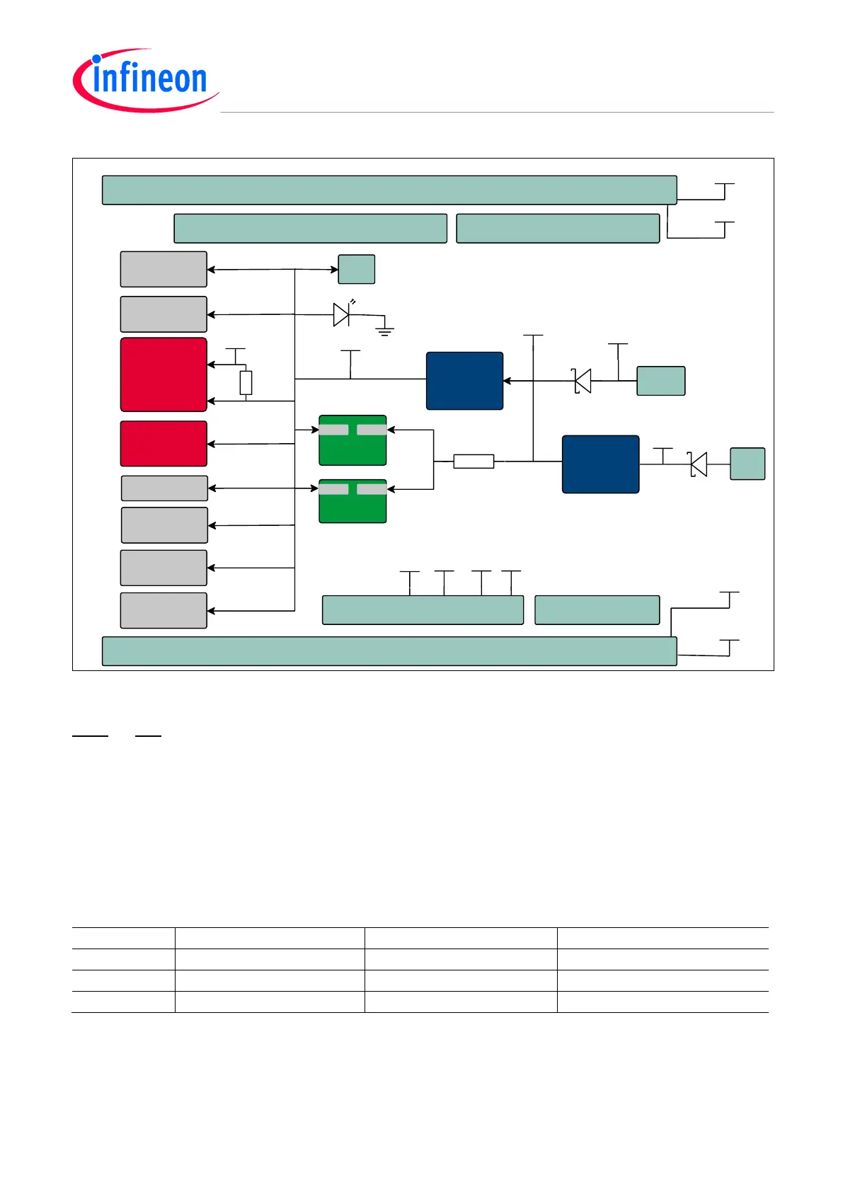
Figure 4 Power Supply Concept
Note: Do not apply any voltage on the mentioned power pins, if the USB is plugged in or any voltage is applied
via DC plug. Furthermore, do not apply multiple sources on the power pins, otherwise you risk to damage and
destroy the board.
2.2 User Push Buttons, User LEDs and Potentiometer
The AURIX lite Kit V2 provides one user push button, a reset button, two LEDs and one potentiometer.
Additionally, LED3 can be used for visualizing an emergency stop function at ESR0 (emergency service request).
The LEDs LED5 and LED6 are used for visualizing activites via the on-board miniWiggler. The port pins used can
be found in Table 2 and Table 4.
Table 2 AURIX Pin Mapping for User LEDs
Name
AURIX Pin
Color
Active
LED1
P00.5
green
Low-active (pull against GND)
LED2
P00.6
green
Low-active (pull against GND)
LED3
ESR0
red
Low-active (pull against GND)

Table of Contents

Related product manuals