EasyManua.ls Logo

Infineon SAK-TC375TP-96F300W AA - Shield2 Go and MikroBus Pinout

Infineon SAK-TC375TP-96F300W AA
27 pages
To Next Page IconTo Next Page
To Previous Page IconTo Previous Page
Loading...
AURIX lite Kit V2
Hardware Description
Board Users Manual 17 Revision October, 2020
4.2 Shield2Go and MikroBus Pinout
The pin connectors for the Shield2Go Connectors 1 and 2 and the mikroBus can be used to extend the
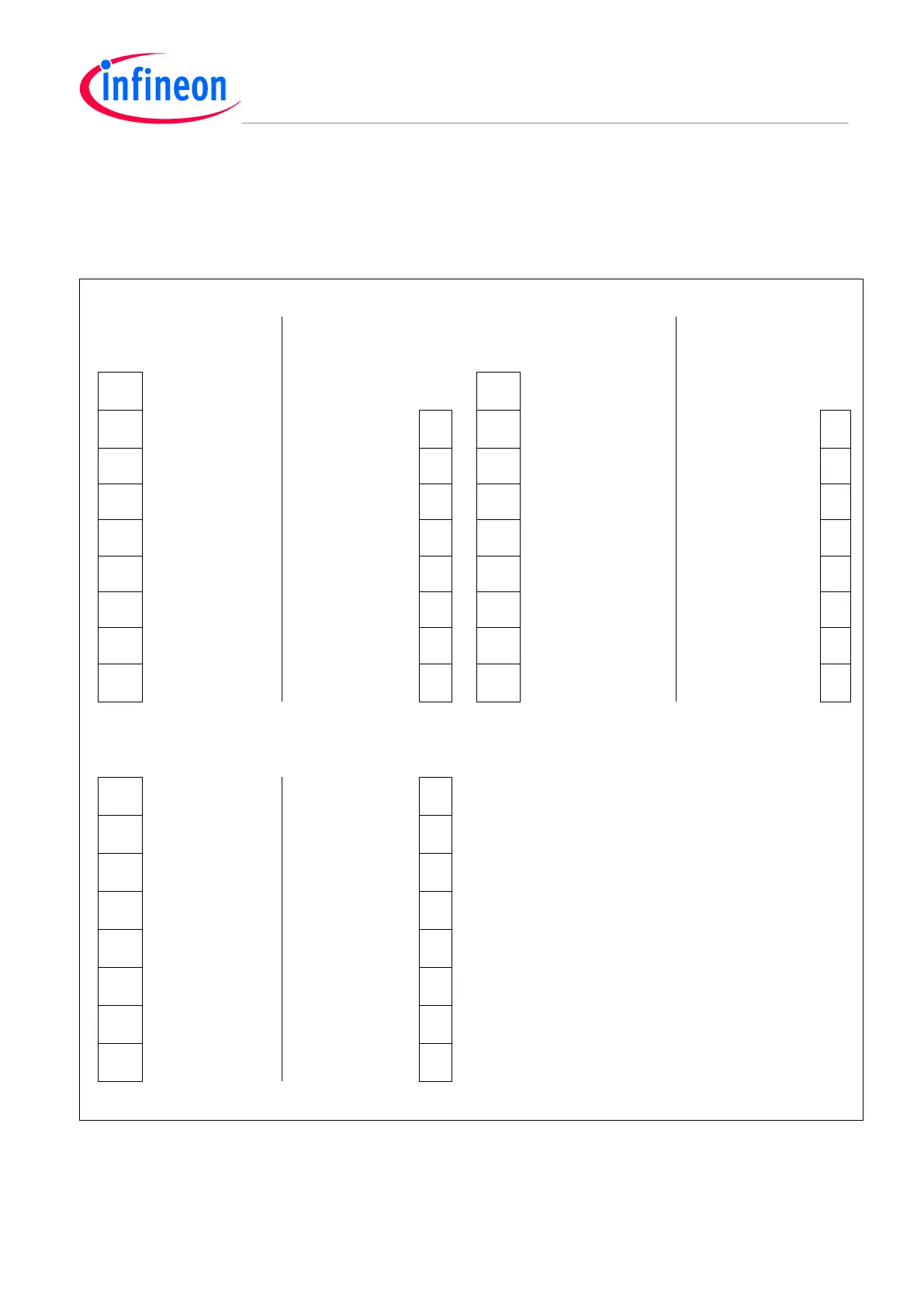
evaluation board or to perform measurements on the AURIX TC3X5/TC2X5. Figure 6 shows the available
signals at these connectors. The pin table is also printed onto the top and bottom side of the AURIX lite Kit V2.
Shield2Go Connector 1
Shield2Go Connector 2
AURIX
Pins
AURIX
Pins
AURIX
Pins
AURIX
Pins
1
+5V
5V
1
+5V
5V
2
AN16
AN1
RX
P33.8
10
2
AN18
AN1
RX
P20.3
10
3
AN17
AN2
TX
P33.9
11
3
AN19
AN2
TX
P20.0
11
4
P13.2
2)
SDA
RST/GPIO2
P23.4
1)
12
4
P13.2
2)
SDA
RST/GPIO2
P23.5
1)
12
5
P13.1
2)
SCL
GPIO1
P32.2
13
5
P13.1
2)
SCL
GPIO1
P32.3
13
6
GND
GND
CS
P20.13
1)
14
6
GND
GND
CS
P20.10
1)
14
7
+3V3
3V3
SCLK
P20.11
1)
15
7
+3V3
3V3
SLCK
P20.11
1)
15
8
P00.4
INT/GPIO3
MOSI
P20.14
1)
16
8
P10.8
INT/GPIO3
MOSI
P20.14
1)
16
9
P14.9
1)
PWM/GPIO4
MISO
P20.12
1)
17
9
P14.10
1)
PWM/GPIO4
MISO
P20.12
1)
17
mikroBus Connector
1
AN26
AN
PWM
P2.8
16
2
P10.6
RST
INT
P10.7
15
3
P14.7
1)
CS
RX
P15.1
14
4
P15.8
1)
SCK
TX
P15.0
13
5
P15.7
1)
MISO
SCL
P13.1
2)
12
6
P15.6
1)
MOSI
SDA
P13.2
2)
11
7
+3V3
3.3V
5V
+5V
10
8
GND
GND
GND
GND
9
Figure 6 Signal mapping of the pin headers for Mikrobus and Shield2Go Connector 1 and 2
Note:
1)
Different signal compared with AURIX™ TC275 lite Kit V1.x
2)
The I2C buses SCL and SDA are shared on the Shield2GOs, mikroBus, Arduino connectors and the I2C eeprom.

Table of Contents

Related product manuals