2 EvalBoard description
The evaluation board (EvalBoard) is a ready-to-use printed circuit board (PCB) which contains:
• The 3D magnetic sensor TLE493D-A2B6. For the availability of 3D Magnetic Sensor 2 Go kits with dierent
sensor variants check the Infineon web page: https://www.infineon.com/cms/en/product/sensor/
magnetic-position-sensor/3d-magnetic-sensor/
• XMC1100 microcontroller based on ARM Cortex
™
-M0 at 48 MHz frequency connected to the 3D sensor.
• XMC4200 microcontroller based on ARM Cortex
™
-M4 at 144 MHz frequency used for the debugging and the
USB communication.
• Micro USB connector for power supply and communication with the Graphical User Interface (GUI).
• LED for indication of power supply and debugging.
• Two LEDs for user configuration.
• Voltage regulator, reverse current protection diode and ESD protection diode.
• Pin headers to access data lines (e.g. via oscilloscope, external microcontroller).
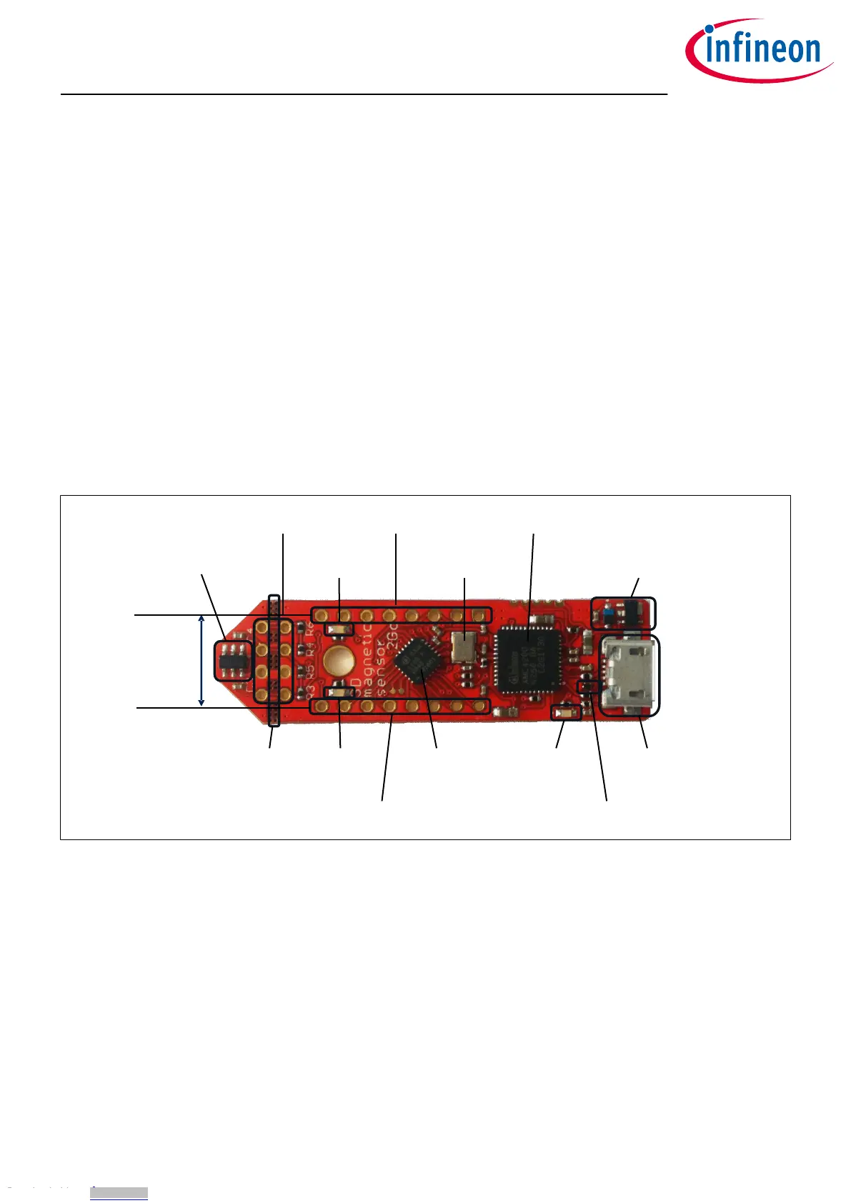
The dierent components and its location are shown in Figure 5. The 3D magnetic sensor can be separated
from the rest of the EvalBoard by cutting the break line.
pin header X3
user LED2
@P1.1
pin header X1
crystal for
debug IC
XMC4200 debug IC and
UART to USB bridge
voltage regulator and reverse
current protection diode
TLE493D-A2B6
mirco USB
connector
ESD protection
diode
power and
debug LED
XMC 1100
mircocontroller
pin header X2
user LED1
@P0.12
break
line
pin header
distance fits
to breadbord
Figure 5 Main components of the EvalBoard
2.1 Optional external power supply
The 3D Magnetic Sensor 2 Go EvalBoard is supplied via the USB cable. It is also possible to provide an external
power supply. If this is the case, a few considerations must be taken into account as described below.
The 3D Magnetic Sensor 2 Go EvalBoard must be supplied by external 5 Volt DC power supply connected to the
micro USB plug. The voltage regulator shis the voltage level to 3.3 V for the microcontrollers and the 3D
magnetic sensor. The Power & Debug LED indicates that the presence of the generated 3.3 V supply voltage.
Out of the box with the pre-programmed application and the on-board debugger in operation the EvalBoard
typically draws about 75 mA. This current can be delivered via the USB plug of a PC, which is specified to deliver
up to 500 mA. An on-board reverse current protection diode will ensure safe operation and protects the USB
port of the Laptop/PC in case power is provided through the pin header X1.
3D Magnetic Sensor 2 Go - TLE493D-A2B6
Low Power 3D Hall Sensor with I²C Interface
EvalBoard description
User Manual 6 1.0
2018-05-16
Downloaded from Arrow.com.Downloaded from Arrow.com.Downloaded from Arrow.com.Downloaded from Arrow.com.Downloaded from Arrow.com.Downloaded from Arrow.com.