31
VIII. UPS REMOTE MONITORING AND CONTROL
Following external connections are available for PDSP series UPSs.
• Communication by serial port connection.
• Dry contact (interface board) connections.
• Remote monitoring panel.
8.1 Using Serial Port
A standard Serial (RS232) communication port is installed to all PDSP series UPS. By using this port user can
get all information about the UPS. All measured parameters and alarms can be monitored via this port. This
port is interactive and some commands for UPS operation are available. These commands are listed below.
• Switch to BYPASS
• Switch to INVERTER
• SOUND on/off
• Adjust UPS time and date
• Start SIMULATION mode
• Quick BATTERY TEST
• BATTERY TEST until battery low alarm
• CANCEL battery test
• Turn off UPS output voltage immediately (SHUTDOWN)
• Turn off UPS output voltage after delay (WAITING SHUTDOWN)
• Turn off UPS output voltage (SHUTDOWN) and turn on UPS output voltage (WAITING RESTART)
• CANCEL SHUTDOWN
• RENAME UPS
UPS will give response to these commands only if the REMOTE: ENABLE option is selected from OPTIONS
MENU.
Apply your local distributor, for information on available software for monitoring and controlling the UPS.
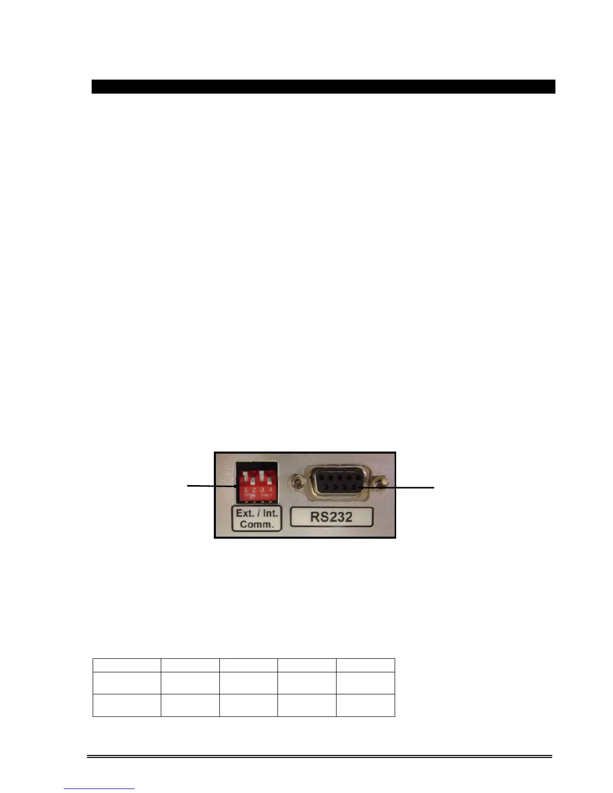
8.1.1 Communication Routing Switch:
RS232 Communication of the UPS can be routed either to an internal (e.g ML100 port multiplexer, MD1
MODBUS adapter, SNMP unit etc.) or to an external device.
There are two sets of DIP switch positions:
1 2 3 4
INTERNAL
(e.g. SNMP)
ON OFF ON OFF
RS232
(EXTERNAL)
OFF ON OFF ON
Communication Routing
DIP Switch
RS232
Communication Port
(DB9 Female)
Figure 8.