22
If this mode is active, you will see ‘’REDUNDT. MODE/MS’’ on the LCD panel of one of the UPS units, and
you will see ‘’REDUNDT. MODE/SL’’ on the LCD panels of all the other UPS units connected in the parallel
system.
As explained above, higher degree of reliability for supplying a critical load can be obtained by choosing
REDUNDANT mode for parallel operation and using as many as possible parallel connected UPSs.
4.2.3. N+1 REDUNDANT mode
This mode is used for operation of at least three (2+1 configuration) UPS units connected in parallel for
increased reliability. If this mode is selected, the load is shared equally by each UPS available in the parallel
system (N+1 numbers of UPS units), during normal operation.
In case of a failure of any one of the UPS units, the faulty UPS is isolated from the parallel system and the
critical load is supplied by the remaining N number of UPSs. If any one of those UPS units fails too, then the
critical load is transferred to bypass supply via the static bypass switches of the parallel connected UPSs. If
the faulty UPS returns to normal operation, it joins the parallel system again and starts sharing the load.
In N+1 REDUNDANT parallel mode, the total VA rating of the parallel system is equal to the VA rating
of a single UPS multiplied by N.
If this mode is active, you will see ‘’N+1 REDUNDANT/MS’’ on the LCD panel of one of the UPS units, and you
will see ‘’N+1 REDUNDANT/SL’’ on the LCD panels of all the other UPS units connected in the parallel
system.
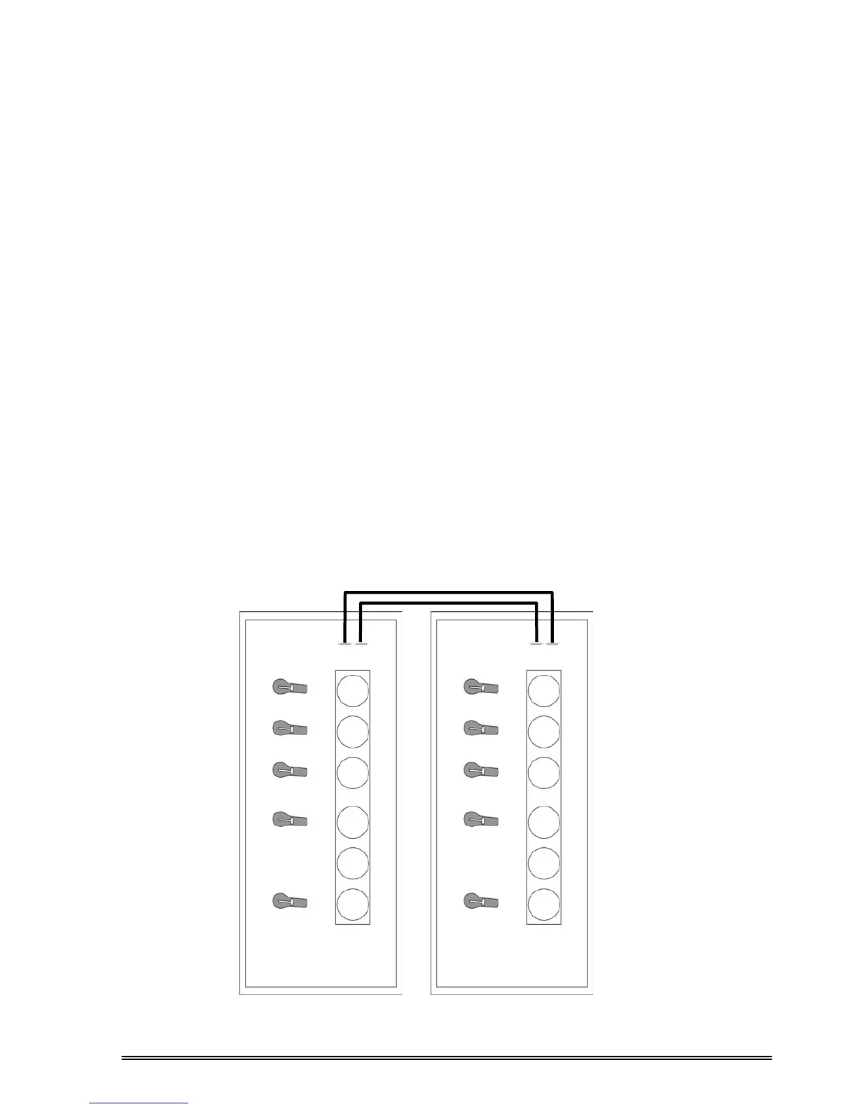
More detailed diagrams for two (or more) PDSP series UPSs connected in parallel are given in Figures 4.2
and 4.3
Figure 4.2 PDSP Series Parallel UPS Signal Cable Connections
Parallel
Port 1
Parallel
Port 2
Figure 4.2.a 2 units in parallel
Parallel
Port 1
Parallel
Port 2