23
Note:
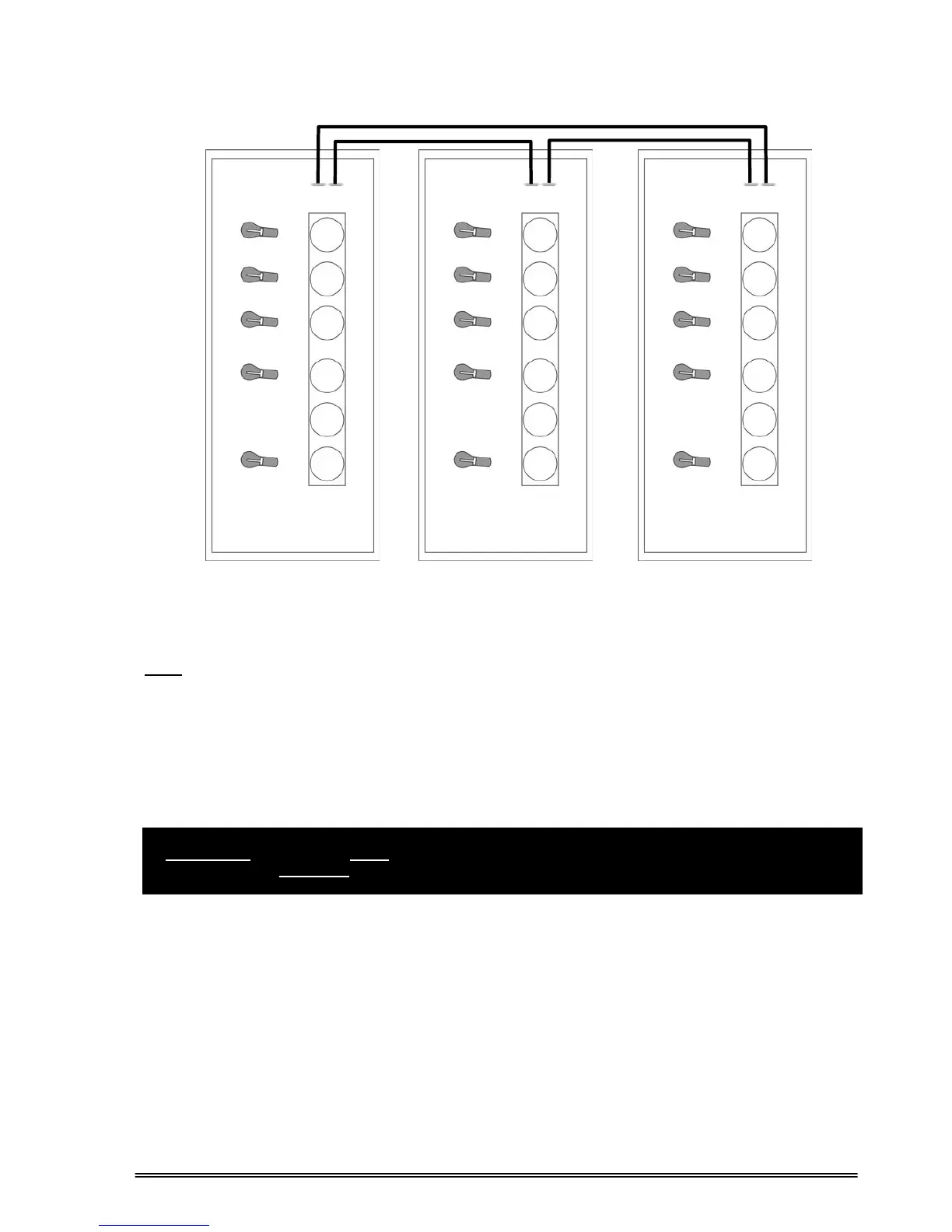
One purpose-built signal cable (DB25) is provided for each UPS unit in the parallel system. Parallel
signal cables are interconnected between the UPS units to form a loop, as shown in figure 4.2, for having
higher reliability against any possible signal cable failures.
After completing the parallel connection of all the UPS units as shown in Figures 4.2 and 4.3, turn on each
UPS unit one by one and select the operation mode and assign a UPS No, using OPTIONS MENU.
All the units must be set for the same operation mode and must have a different UPS number.
CAUTION !!! You must never set the operation modes of parallel connected UPS units to
“ONLINE”, otherwise serious damage may occur in UPSs.
Figure 4.2.b 3 units in parallel
Parallel
Port 1
Parallel
Port 2
Parallel
Port 1
Parallel
Port 2
Parallel
Port 1
Parallel
Port 2