7
Otherwise, the UPS and the load connected to the output will be left ungrounded. The grounding system
must be checked, and must be strengthen if required. Potential difference between ground and neutral
must be less than 3V AC.
Descriptions of the UPS input output cable connection terminals are shown in figure 2.1
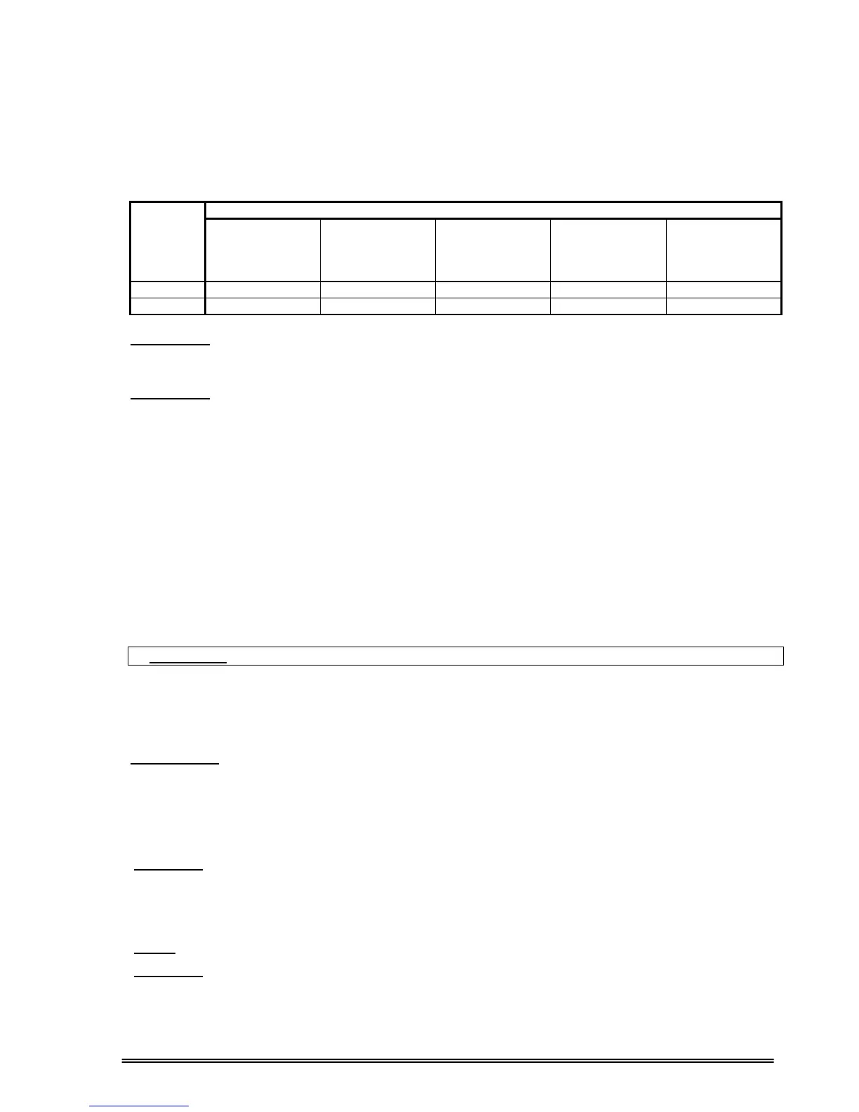
Recommended input line cable and fuse ratings are given in the table below.
Recommended cable size (mm
2
)
UPS
RATING
(KVA)
AC INPUT
Bypass INPUT
/ AC OUTPUT
External
Battery
INPUT
AC Input /AC
Output Cable
Terminals
U-V-W-N
Battery
Terminals
+ & -
120 50 50 70 M8 bolt M8 bolt
160 70 70 70 M8 bolt M8 bolt
NOTES :
The neutral conductor should be sized for 1,5 times the output/bypass phase current. These
recommendations are for guideline purposes only and are superceded by local regulations
and codes of practice.
WARNING :
THERE ARE NO INTERNAL FUSES ON THE BYPASS INPUT AND ON THE AC OUTPUT
OF THE UPS. THEREFORE, IT IS RECOMMENDED THE USE EXTERNAL FUSES OR
MCCBS OF SUITABLE RATINGS BOTH ON THE AC INPUT AND OUTPUT OF THE UPS.
2.7.1 Safety Earth
The safety earth cable must be connected to the earth BUSBAR and bonded to each cabinets in the system
and also the grounding and neutral bonding arrangements must be in accordance with the local laws.
ATTENTION!!! Failure to follow adequate grounding procedures can result in electric shock hazard to
personnel, or the risk of fire.
2.7.2 Cable connection procedure
WARNING!!! All connections of the UPS must be done by qualified service personnel
After positioning the UPS, the cables must be connected as described below:
1. Verify all switches in front of the UPS are at “0” position. (OFF)
2. Connect the 3 phase AC input coming from the mains distribution panel to the AC input terminals as shown
on the label. (Figure 2.1)
ATTENTION!!!: ENSURE CORRECT PHASE SEQUENCE.
If there is a phase sequence error, UPS doesn’t transfer the load to INVERTER output. If
you can’t see SYNC:OK in the INFORMATION MENU on LCD, then change the input
phase sequence.
3. Connect the output of the UPS to the load distribution panel.
4. Connect the battery groups. Refer to battery installation section.
WARNING:
- CHECK BOTH OF THE BATTERY GROUPS FOR CORRECT POLARITY AND VOLTAGE
- DO NOT TURN ON THE BATTERY SWITCH (S5) BEFORE STARTING THE UPS
5. Connect the copper earth bus, to the safety earth of the mains distribution panel.
NOTE: The earth and the neutral connections must be in accordance with the local rules.
WARNING: NEVER TURN ON THE UNIT WITHOUT AN INPUT NEUTRAL CONNECTION (N1).