2
• Remote monitoring Panel (Optional)
• RS232 port multiplexer (Optional)
• MODBUS adapter (Optional)
• Diagnostic and adjustment via PC.
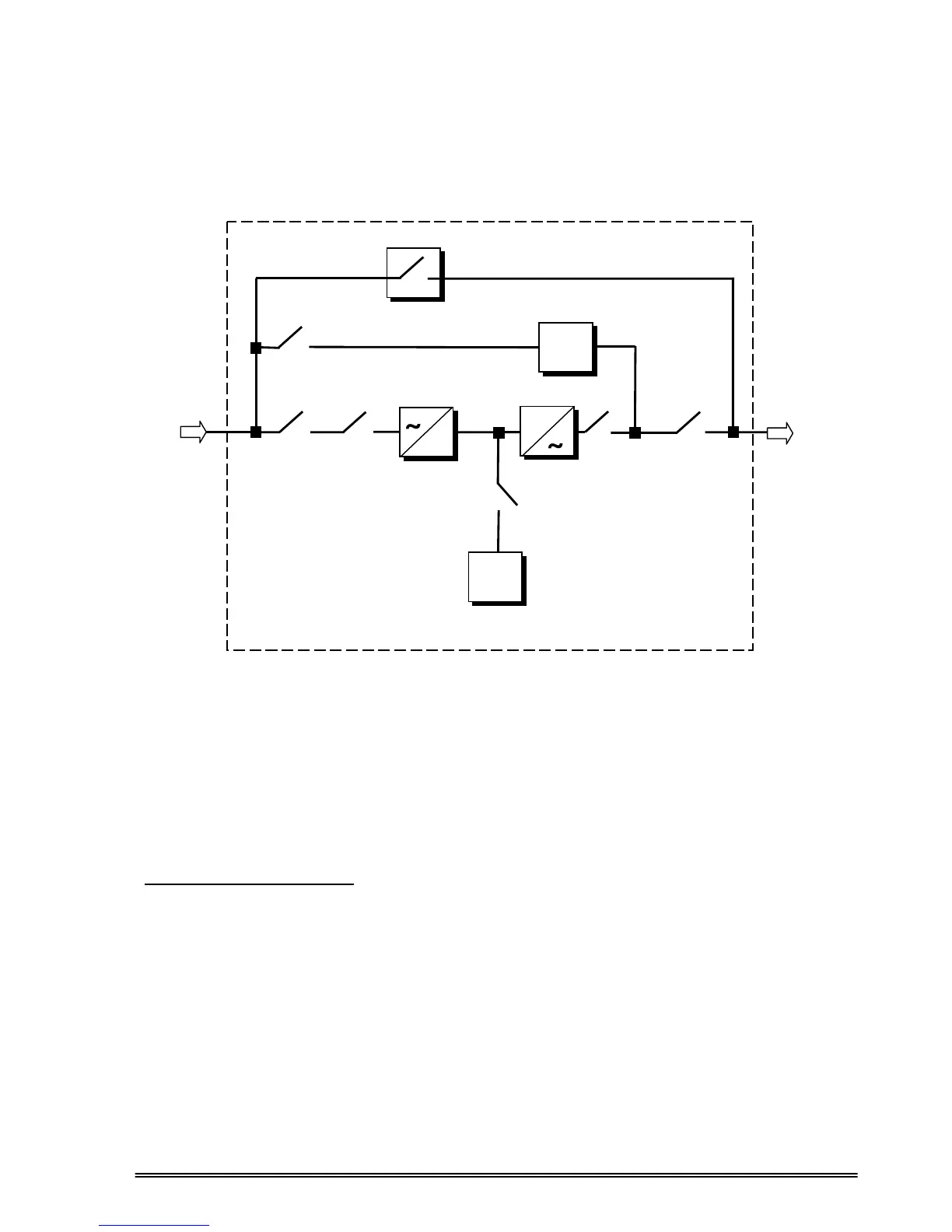
1.2 Design Concept
Figure 1.1 Block Diagram Of The UPS
S1 (F1-F2-F3) : Rectifier Input Switch / Fuses
S2 (F4-F5-F6) : Bypass Input Switch
S3 : Maintenance Bypass Switch
S4 (F7-F8-F9) : Output Switch
S5 (F10-F11-F12) : Battery Switch / Fuses
K1 : Rectifier Input Contactor
K2 : Inverter Output Contactor
DESCRIPTION OF BLOCKS
RECTIFIER: In PDSP Series UPSs, a PWM controlled IGBT rectifier is used to increase input power factor
(PFC) and to decrease input current harmonics (THDI).
The IGBT rectifier accepts 3-phase AC input and produces a dual polarity DC voltage for both supplying the
inverter and charging the batteries.
BATTERIES: Batteries are used as reserve DC power supply for the Inverter in case of mains failure. In
PDSP Series, batteries are connected in series with a center-tap output to obtain a dual polarity DC supply.
Batteries are discharged by the inverter during mains failure. The discharged batteries are re-charged by the
IGBT Rectifier on a constant current / constant voltage basis, if AC mains power is available.
INVERTER: It is manufactured by using the latest IGBT technology and Pulse width Modulation (PWM)
technique. The Inverter converts the DC BUS voltage supplied by the IGBT Rectifier and / or the batteries into
a well regulated 3-phase AC voltage with fixed voltage and frequency.
The output of the inverter is used to supply the critical loads connected to the UPS output.
Rectifier /
Charger
3 PHASE
MAINS I/P
Battery
(Dual Polarity)
Maintenance Bypass Switch
Static Bypass
S2
(F4-F5-F6)
S1