Connecting to the Telephone Network
Honeywell Security recommends that the Informa
be connected to an ex-directory standard PSTN
telephone line, and that ideally no other telephone
apparatus is connected to the same line.
The Informa may be connected to the telephone
network by either of the two methods below:
a) Using the supplied RJ-11 telecoms lead and
suitable adapter to plug into a standard
telephone socket.
b) Using a direct connection to a BT master jack
socket using a special telephone cable, see page
7, Connecting Directly to a Master Jack.
Using the Supplied Telephone Lead
This two-way lead must be wired to the terminals
on the Informa PCB as follows:
Wire Colour PCB Terminal
White A
Red B
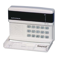
Connecting Directly to a Master Jack
Direct connection to a master jack socket should be
undertaken by an approved installer, using the
connections described below.
The cable used to connect the Informa to the master
socket must conform to BT specification CW1308.
This has a single-strand conductor of 0.5mm2. On
no account should any other type of cable be used.
At the master socket identify the terminals A and B.
This can be done either by reference to the terminal
numbers on the socket, or by the wiring code.
Connect one end of the telephone cable to the
Informa terminals labelled A and B. Strip back 5mm
of insulation from each of the two conductors, insert
the conductors into the terminal block and tighten the
screw. The telephone cable should be routed away
from all other cables inside the housing.
Connect the other end of the telephone cable to the
master socket. It may be necessary to use a special
IDT termination tool to do this securely.
Terminal Number Wire Colour
A 5 White with blue rings
B 2 Blue with white rings
c) Program the INH input as Active High.
ote that if the Follow Me function is enabled in
a Bells Only panel, a bell test will cause the
dialler to start the call procedure, because the
SET+ or SET connection to IH does not prevent
dialling when the panel is unset.
Refer to page 3, The Follow Me Function.