12
2.3.0 Main protections
2.3.1 Stored protections
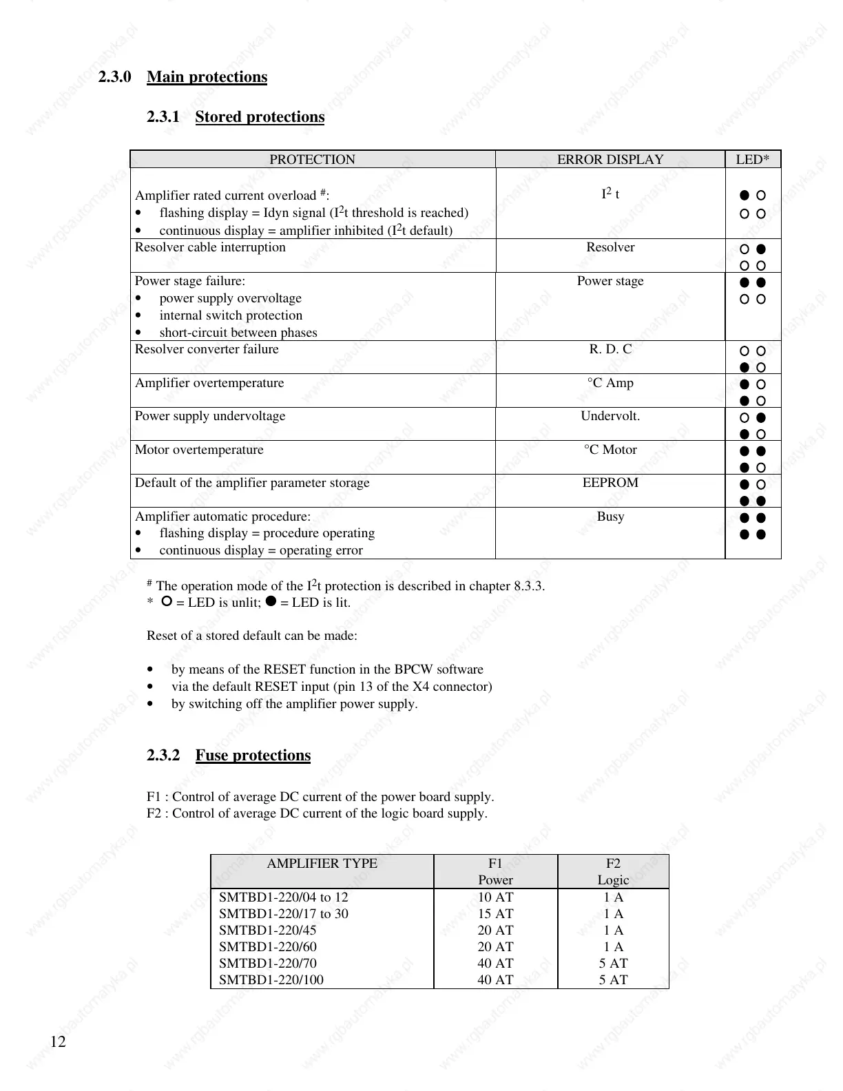
PROTECTION ERROR DISPLAY LED*
Amplifier rated current overload
#
:
I
2
t
• flashing display = Idyn signal (I
2
t threshold is reached)
• continuous display = amplifier inhibited (I
2
t default)
Resolver cable interruption Resolver
Power stage failure: Power stage
• power supply overvoltage
• internal switch protection
• short-circuit between phases
Resolver converter failure R. D. C
Amplifier overtemperature °C Amp
Power supply undervoltage Undervolt.
Motor overtemperature °C Motor
Default of the amplifier parameter storage EEPROM
Amplifier automatic procedure: Busy
• flashing display = procedure operating
• continuous display = operating error
#
The operation mode of the I
2
t protection is described in chapter 8.3.3.
* = LED is unlit; = LED is lit.
Reset of a stored default can be made:
• by means of the RESET function in the BPCW software
• via the default RESET input (pin 13 of the X4 connector)
• by switching off the amplifier power supply.
2.3.2 Fuse protections
F1 : Control of average DC current of the power board supply.
F2 : Control of average DC current of the logic board supply.
AMPLIFIER TYPE F1 F2
Power Logic
SMTBD1-220/04 to 12 10 AT 1 A
SMTBD1-220/17 to 30 15 AT 1 A
SMTBD1-220/45 20 AT 1 A
SMTBD1-220/60
SMTBD1-220/70
20 AT
40 AT
1 A
5 AT
SMTBD1-220/100 40 AT 5 AT
 Loading...