37
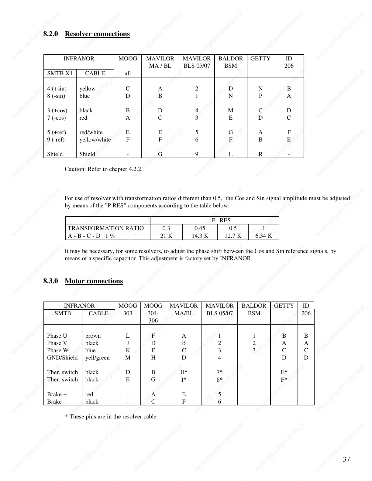
8.2.0 Resolver connections
INFRANOR MOOG MAVILOR
MA / BL
MAVILOR
BLS 05/07
BALDOR
BSM
GETTY ID
206
SMTB X1 CABLE all
4 (+sin) yellow C A 2 D N B
8 (-sin) blue D B 1 N P A
3 (+cos) black B D 4 M C D
7 (-cos) red A C 3 E D C
5 (+ref) red/white E E 5 G A F
9 (-ref) yellow/white F F 6 F B E
Shield Shield - G 9 L R -
Caution: Refer to chapter 4.2.2.
For use of resolver with transformation ratios different than 0,5, the Cos and Sin signal amplitude must be adjusted
by means of the "P RES" components according to the table below:
P RES
TRANSFORMATION RATIO 0.3 0.45 0.5 1
A - B - C - D 1 % 21 K 14.3 K 12.7 K 6.34 K
It may be necessary, for some resolvers, to adjust the phase shift between the Cos and Sin reference signals, by
means of a specific capacitor. This adjustment is factory set by INFRANOR.
8.3.0 Motor connections
INFRANOR MOOG MOOG MAVILOR MAVILOR BALDOR GETTY ID
SMTB CABLE 303 304-
306
MA/BL BLS 05/07 BSM 206
Phase U brown L F A 1 1 B B
Phase V black J D B 2 2 A A
Phase W blue K E C 3 3 C C
GND/Shield yell/green M H D 4 D D
Ther. switch black D B
H* 7* E*
Ther. switch black E G
I* 8* F*
Brake + red - A E 5
Brake - black - C F 6
* These pins are in the resolver cable
 Loading...