14
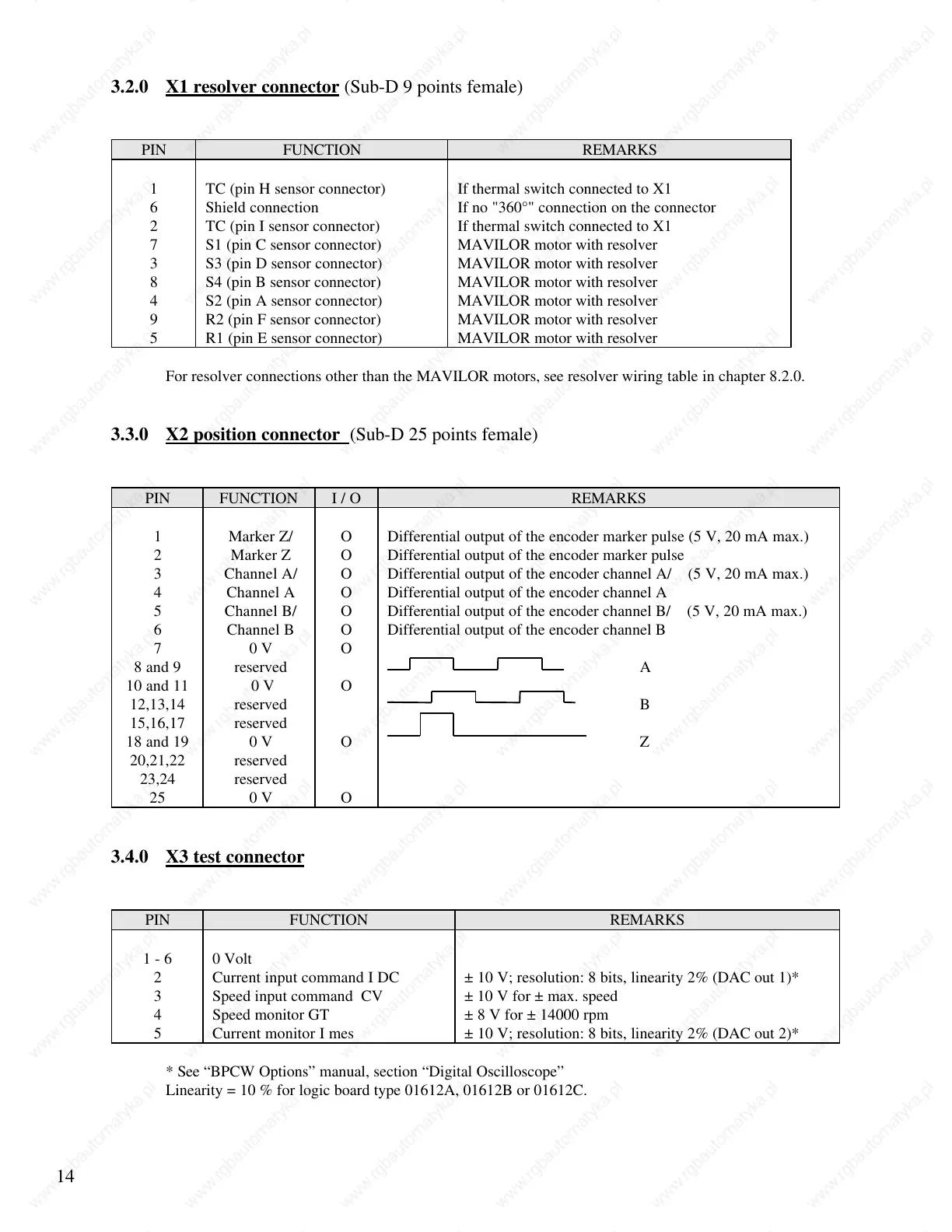
3.2.0 X1 resolver connector (Sub-D 9 points female)
PIN FUNCTION REMARKS
1 TC (pin H sensor connector) If thermal switch connected to X1
6 Shield connection If no "360°" connection on the connector
2 TC (pin I sensor connector) If thermal switch connected to X1
7 S1 (pin C sensor connector) MAVILOR motor with resolver
3 S3 (pin D sensor connector) MAVILOR motor with resolver
8 S4 (pin B sensor connector) MAVILOR motor with resolver
4 S2 (pin A sensor connector) MAVILOR motor with resolver
9 R2 (pin F sensor connector) MAVILOR motor with resolver
5 R1 (pin E sensor connector) MAVILOR motor with resolver
For resolver connections other than the MAVILOR motors, see resolver wiring table in chapter 8.2.0.
3.3.0 X2 position connector (Sub-D 25 points female)
PIN FUNCTION I / O REMARKS
1 Marker Z/ O Differential output of the encoder marker pulse (5 V, 20 mA max.)
2 Marker Z O Differential output of the encoder marker pulse
3 Channel A/ O Differential output of the encoder channel A/ (5 V, 20 mA max.)
4 Channel A O Differential output of the encoder channel A
5 Channel B/ O Differential output of the encoder channel B/ (5 V, 20 mA max.)
6 Channel B O Differential output of the encoder channel B
7 0 V O
8 and 9 reserved A
10 and 11 0 V O
12,13,14 reserved B
15,16,17 reserved
18 and 19 0 V O Z
20,21,22 reserved
23,24 reserved
25 0 V O
3.4.0 X3 test connector
PIN FUNCTION REMARKS
1 - 6 0 Volt
2 Current input command I DC ± 10 V; resolution: 8 bits, linearity 2% (DAC out 1)*
3 Speed input command CV ± 10 V for ± max. speed
4 Speed monitor GT ± 8 V for ± 14000 rpm
5 Current monitor I mes ± 10 V; resolution: 8 bits, linearity 2% (DAC out 2)*
* See “BPCW Options” manual, section “Digital Oscilloscope”
Linearity = 10 % for logic board type 01612A, 01612B or 01612C.
 Loading...