16
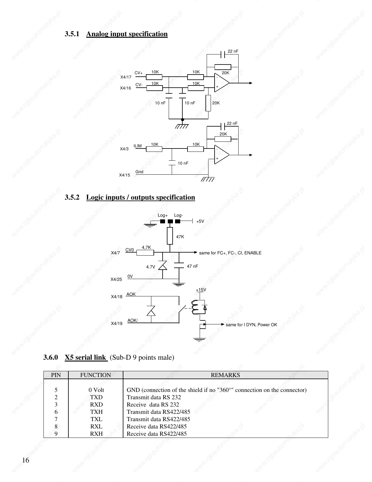
3.5.1 Analog input specification
+
-
10K
10K
10K
10K
20K
20K
22 nF
10 nF 10 nF
X4/16
X4/17
CV+
CV-
+
-
10K 10K
20K
22 nF
10 nF
X4/15
X4/3
ILIM
Gnd
3.5.2 Logic inputs / outputs specification
47K
+5V
4,7K
47 nF
X4/7
CV0
X4/25
0V
4.7V
Log+ Log-
+15V
X4/18
AOK
X4/19
AOK/
same for FC+, FC-, CI, ENABLE
same for I DYN, Power OK
3.6.0 X5 serial link (Sub-D 9 points male)
PIN FUNCTION REMARKS
5 0 Volt GND (connection of the shield if no "360°" connection on the connector)
2 TXD Transmit data RS 232
3 RXD Receive data RS 232
6 TXH Transmit data RS422/485
7 TXL Transmit data RS422/485
8 RXL Receive data RS422/485
9 RXH Receive data RS422/485
 Loading...