24
Current phase lead parameter defines the current phase lead for the maximum speed of the motor. This
phase lead is proportional to the motor speed and compensates the phase shift of the current loops in order
to keep a maximum torque / current ratio in the motor.
CURRENT PHASE LEAD CALCULATION function calculates the Current phase lead parameter
according to the following motor specifications: Motor torque constant (Nm/A), Motor terminal
inductance (mH) and Motor maximum speed (rpm). This procedure is used for motors which are not
included in the MOTOR LIST module.
5.4.2 Controller parameters
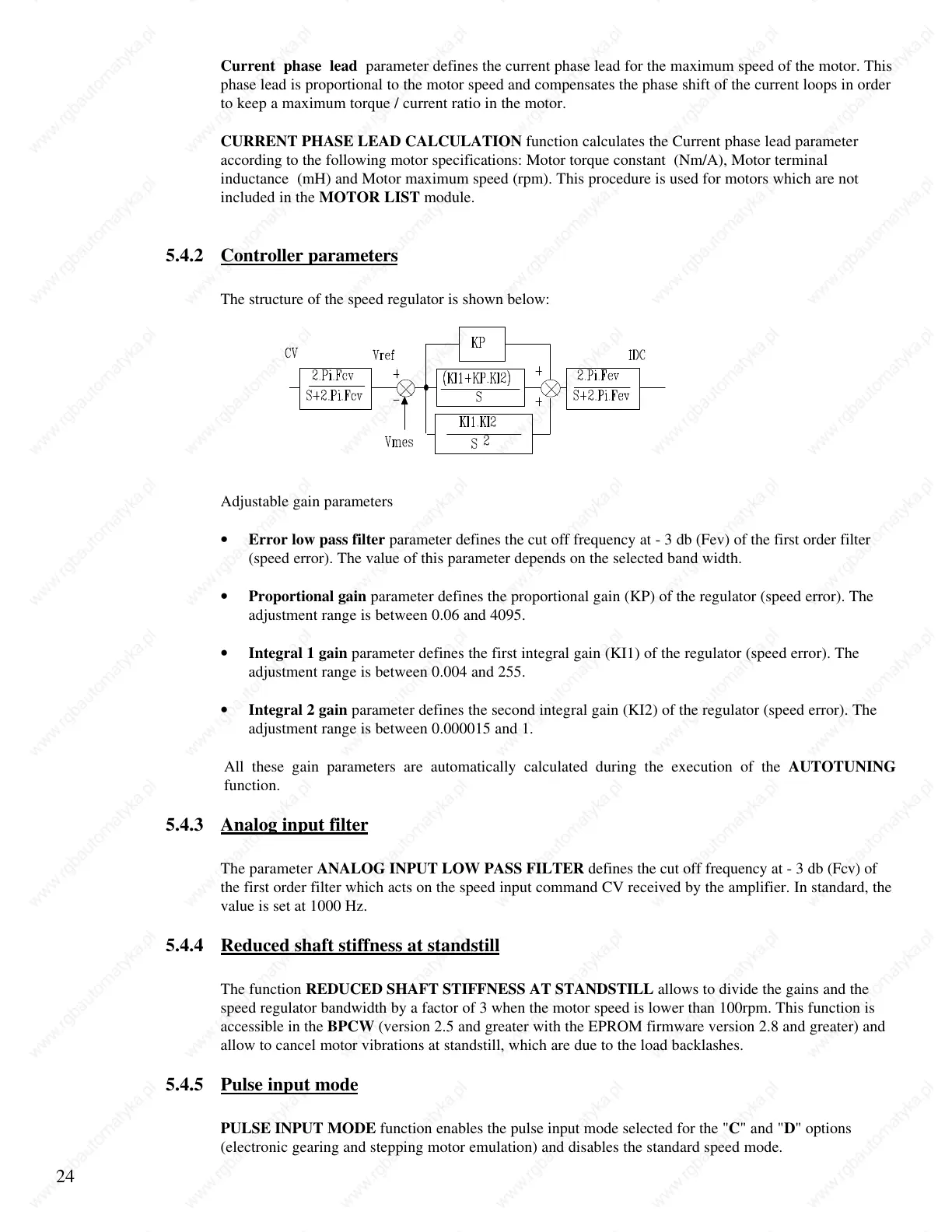
The structure of the speed regulator is shown below:
Adjustable gain parameters
• Error low pass filter parameter defines the cut off frequency at - 3 db (Fev) of the first order filter
(speed error). The value of this parameter depends on the selected band width.
• Proportional gain parameter defines the proportional gain (KP) of the regulator (speed error). The
adjustment range is between 0.06 and 4095.
• Integral 1 gain parameter defines the first integral gain (KI1) of the regulator (speed error). The
adjustment range is between 0.004 and 255.
• Integral 2 gain parameter defines the second integral gain (KI2) of the regulator (speed error). The
adjustment range is between 0.000015 and 1.
All these gain parameters are automatically calculated during the execution of the AUTOTUNING
function.
5.4.3 Analog input filter
The parameter ANALOG INPUT LOW PASS FILTER defines the cut off frequency at - 3 db (Fcv) of
the first order filter which acts on the speed input command CV received by the amplifier. In standard, the
value is set at 1000 Hz.
5.4.4 Reduced shaft stiffness at standstill
The function REDUCED SHAFT STIFFNESS AT STANDSTILL allows to divide the gains and the
speed regulator bandwidth by a factor of 3 when the motor speed is lower than 100rpm. This function is
accessible in the BPCW (version 2.5 and greater with the EPROM firmware version 2.8 and greater) and
allow to cancel motor vibrations at standstill, which are due to the load backlashes.
5.4.5 Pulse input mode
PULSE INPUT MODE function enables the pulse input mode selected for the "C" and "D" options
(electronic gearing and stepping motor emulation) and disables the standard speed mode.
 Loading...