Halley5 Base Board
X2000 Development Kit User Manual
Copyright® 2005-2021 Ingenic Semiconductor Co., Ltd. All rights reserved.
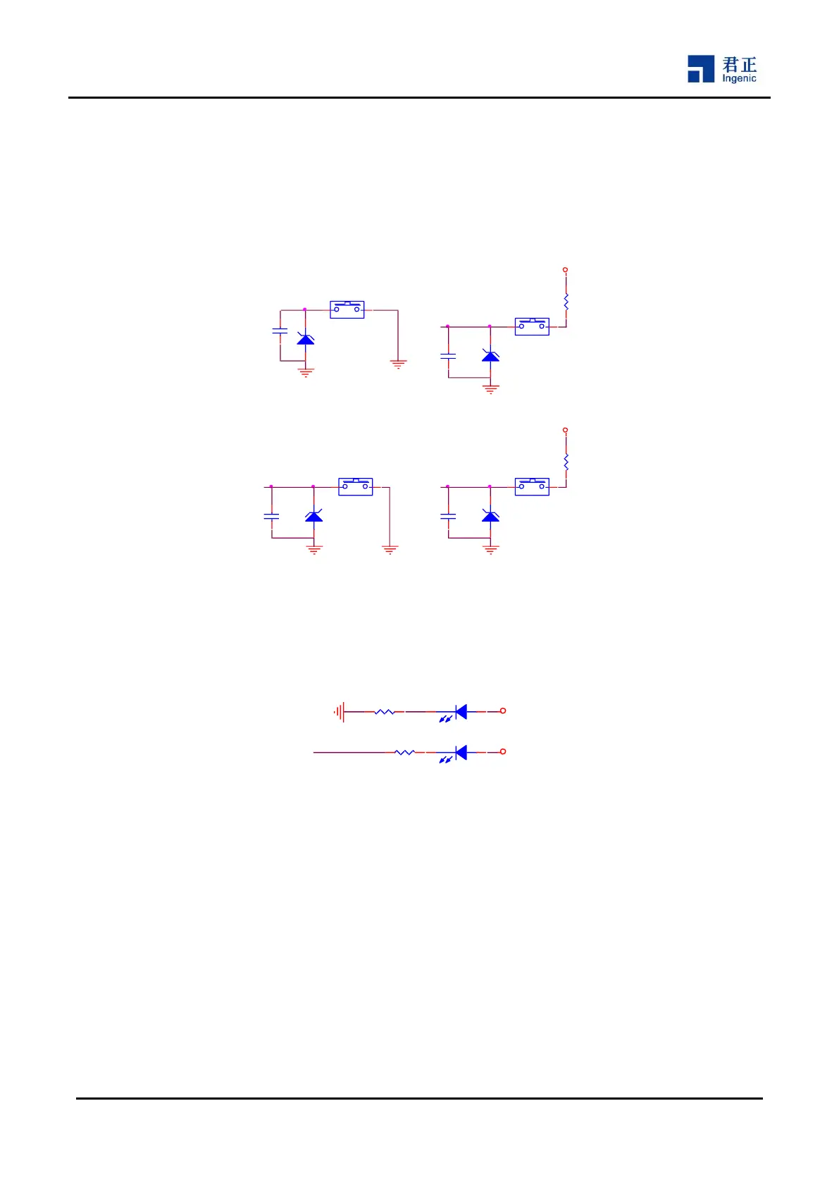
3.2.7 Keys Function Circuit
The base board supports 4 keys, they are: a wakeup key SW5, a hardware reset key SW6, two boot selection
keys SW3 and SW4. After reset, the boot program on the X2000 internal boot ROM will initialize clock and read
boot_sel[2:0] to determine the boot method. Halley5 boot from SPI NAND Flash by default. By pressing SW4,
Halley5 can boot from SD card at MSC2@3.3V, and by pressing SW3, Halley5 can boot from USB (USB boot
is to download code from PC).
Figure 3-7 Halley5 Base Board Keys Circuit
3.2.8 LED Function Circuit
The Halley5 base board supports a system power LED indicator D2 and reset LED indicator D1.
Figure 3-8 Halley5 Base Board LEDs Circuit
3.2.9 OLED Function Circuit
The base board supports a 2-lane MIPI OLED (1080P@40fps) with touch panel, and the SGM3849 provide
4.6V, 6.4V and -4.5V to drive OLED. Figure 3-9 shows the circuit of Halley5 base board.
ESD12
1
2
C563
0.1uF
C564
0.1uF
C565
0.1uF
PPRST_N
C566
0.1uF
R17
1K
SW3
12
SW4
12
SW5
12
SW6
12
WKUP_N BOOT_SEL1
1V8P
1V8P
R18
1K
BOOT_SEL0
ESD11
ESD9X5VU
1
2
ESD10
ESD9X5VU
1
2
ESD13
ESD9X5VU
1
2
R20 300R
D2
12
3V3P
R19 300R
3V3P
D1
PPRST_N