MAINTENANCE
20
M4 M5,5 M7,5 M11
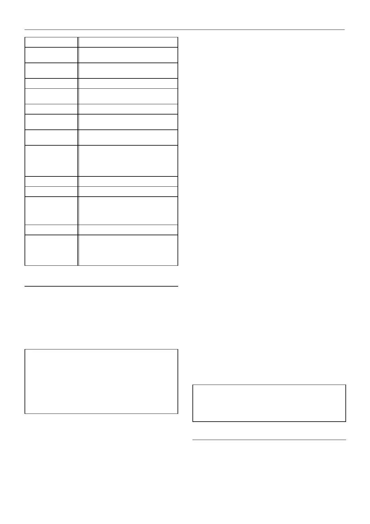
PERIOD MAINTENANCE
Daily
Check the coolant level and replenish if
necessary.
Each week
Check that the safety valve easing gear
moves freely.
First 150 hours Change the coolant filter.
Each 3 months
Check all hoses for signs of deterioration,
cracks, hardening etc.
Each 2000 hours Change the coolant filter.
2000 hours / 6
months
Check the operation of the high
temperature protection switch.
1 year
Remove the safety valve from the
compressor, inspect and re–calibrate.
1 year/1000 hours or
as defined by local
or national
legislation.
Separator tank.
Fully inspect all external surfaces, welds
and fittings. Report any excessive
corrosion, mechanical or impact damage,
leakage or other deterioration.
1 year / 4000 hours Change the air filter element.
4000 hours Change the separator element.
8000 hours / 2 years Replace the ULTRA COOLANT at
whichever interval occurs first.
Also replace the separator element and
coolant filter.
Each 8000 hours Change the drive belts.
6 years/6000 hours
or as defined by
local or national
legislation.
Separator tank.
Remove the cover plate and any
necessary fittings. Clean the interior
thoroughly and inspect all internal surfaces
and welds.
ROUTINE MAINTENANCE
This section refers to the various components which require
periodic maintenance and replacement.
The SERVICE/MAINTENANCE CHART indicates the various
components’ descriptions and the intervals when maintenance has to
take place. Coolant capacities, etc., can be found in the GENERAL
INFORMATION section of this manual.
CAUTION: Before beginning any work on the compressor, open,
lock and tag the main electrical disconnect and close the isolation
valve on the compressor discharge. Vent pressure from the unit
by slowly unscrewing the coolant fill cap one turn. Unscrewing
the fill cap opens a vent hole, drilled in the cap, allowing pressure
to release to atmosphere. Do not remove the fill cap until all
pressure has vented from the unit. Also vent piping by slightly
opening the drain valve. When opening the drain valve or the
coolant fill cap, stand clear of the valve discharge and wear
appropriate eye protection.
Compressed air can be dangerous if incorrectly handled. Before
doing any work on the unit, ensure that all pressure is vented from the
system and that the machine cannot be started accidentally.
Ensure that maintenance personnel are adequately trained,
competent and have read the Maintenance Manuals.
Prior to attempting any maintenance work, ensure that:–
. all air pressure is fully discharged and isolated from the system. If
the automatic blowdown valve is used for this purpose, then allow
enough time for it to complete the operation.
. the machine cannot be started accidently or otherwise, by posting
warning signs and/or fitting appropriate anti–start devices.
. all residual electrical power sources (mains and battery) are
isolated.
Prior to opening or removing panels or covers to work inside
a machine, ensure that:–
. anyone entering the machine is aware of the reduced level of
protection and the additional hazards, including hot surfaces and
intermittently moving parts.
. the machine cannot be started accidently or otherwise, by posting
warning signs and/or fitting appropriate anti–start devices.
Prior to attempting any maintenance work on a running
machine, ensure that:–
. the work carried out is limited to only those tasks which require the
machine to run.
. the work carried out with safety protection devices disabled or
removed is limited to only those tasks which require the machine to be
running with safety protection devices disabled or removed.
. all hazards present are known (e.g. pressurised components,
electrically live components, removed panels, covers and guards,
extreme temperatures, inflow and outflow of air, intermittently moving
parts, safety valve discharge etc.).
. appropriate personal protective equipment is worn.
. loose clothing, jewellery, long hair etc. is made safe.
. warning signs indicating that Maintenance Work is in Progress are
posted in a position that can be clearly seen.
Upon completion of maintenance tasks and prior to returning
the machine into service, ensure that:–
. the machine is suitably tested.
. all guards and safety protection devices are refitted.
. all panels are replaced, canopy and doors closed.
. hazardous materials are effectively contained and disposed of.
WARNING
Do not under any circumstances open any drain valve or remove
components from the compressor without first ensuring that the
compressor is FULLY SHUT– DOWN, power isolated and all air
pressure relieved from the system.
COOLANT CHANGE PROCEDURE
The compressor features a ’no drip’ coolant drain feature which
requires no special tools and minimises the risk of coolant spillage.
It is better to drain the coolant immediately after the compressor has
been operating as the liquid will drain more easily and any contaminant
will still be in suspension.
1. Remove the cap from the drain valve located at the front of the
separator vessel.
 Loading...