14
6.3 Setting Menu Instruction
6.4 Control Function Instruction
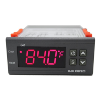
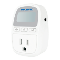
When the controller works normally, PV
screen shows the measured temperature,
meantime the SV screen shows the set
temperature. It recognizes and converts
from heating to cooling mode automatical-
ly. HEATING socket for heating output, the
red LED indicator showing heating status.
While COOLING socket for cooling output,
the green LED indicator showing cooling
status.
6.4.1 Instructions for Setting Temperature
Control (TS, HD, CD)
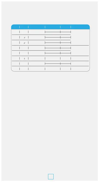
TS
HD
Temperature Setting
Value
Heating Difference
Value
-40.0°C~100°C
-40.0°F~212°F
0.3°C~15.0°C
1.0°F~30.0°F
More details on 6.4.1
More details on 6.4.4
More details on 6.4.5
More details on 6.4.3
More details on 6.4.2
25.0°C
77.0°F
2.0°C
3.0°F
CA
CF
H
CD
Cooling Difference
Value
0.3°C~15.0°C
1.0°F~30.0°F
2.0°C
3.0°F
C
AH
Alarm High
Temperature Limit
-40.0°C~100°C
-40.0°F~212°F
100°C
212°F
AH
P
Code Symbol Function Setting Range
Default
Settings
Annotation
AL
Alarm High
Temperature Limit
-40.0°C~100°C
-40.0°F~212°F
-40.0°C
-40.0°F
AL
PT
Compressor Delay
Time
0~10 minutes
minute
CA
Temperature
Calibration
-9.9°C~9.9°C
-15.0°F~15.0°F
0.0°C
0.0°F
CF
Fahrenheit or Celsius
Settings
C or F F
tS
 Loading...