10
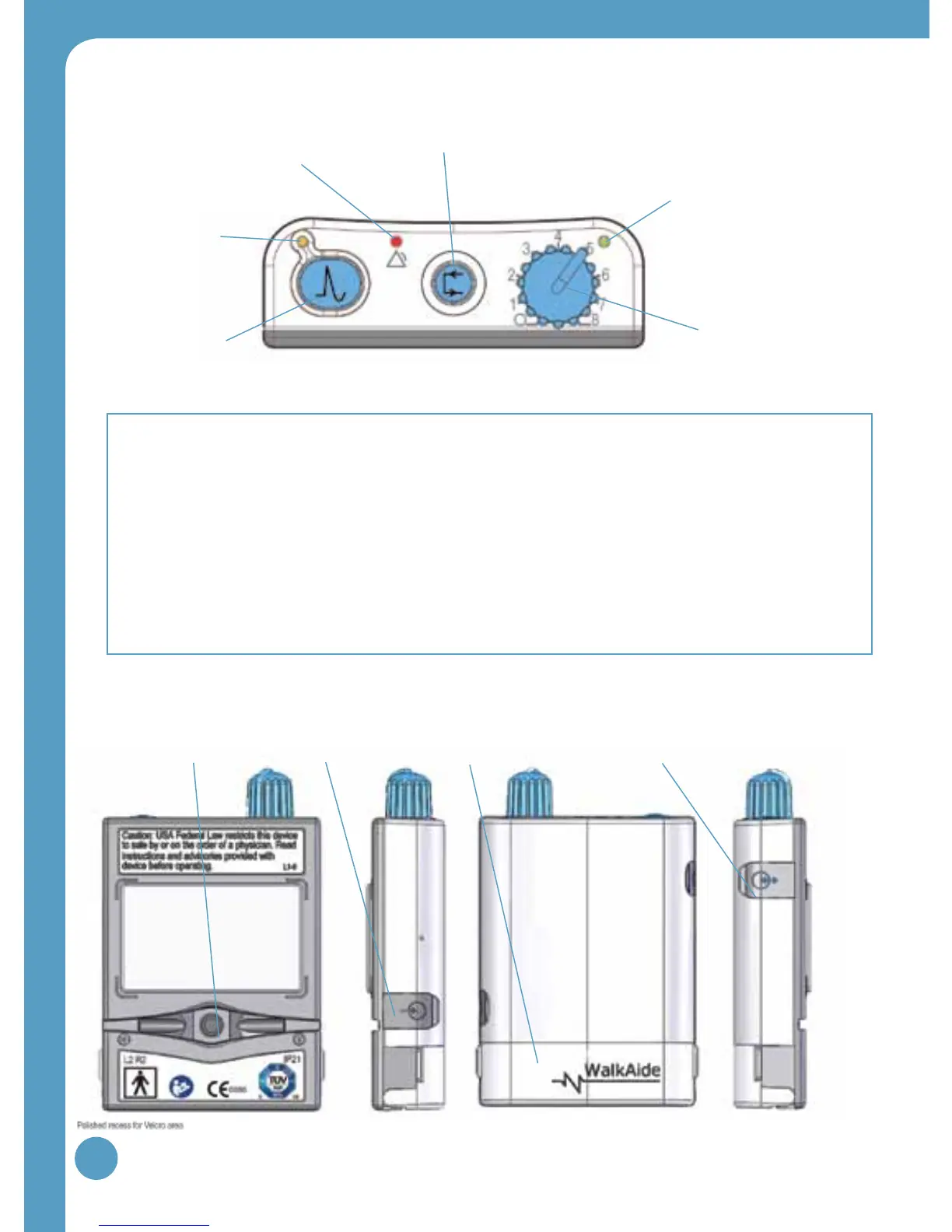
Figure 3: Back, side(s) and front views of WalkAide unit
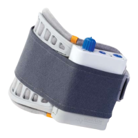
Red visual indicator for error
and low battery voltage (4)
Figure 2: Top view of WalkAide unit
3.0 WalkAide Controls and Indicators
Output Connector
for Electrode Lead
Cable (7)
WalkLink Connector
[for clinician use only] (10)
Battery Compartment
for standard AA
Alkaline battery (9)
Heel and Foot Sensor
Connector
[if provided to user] (8)
Exercise Button (3)
Audible Alarms:
1. Low Battery: An audible alarm every minute with red and green blinking lights.
2. Depleted Battery: An audible alarm every 1-2 seconds with red and green blinking lights
3. Heel/Foot Sensor: An audible alarm of two beeps every two seconds indicates that Heel/Foot
Sensor is not connected, if it is configured for the Heel/Foot Sensor.
4. Device Error: An audible alarm of 4 beeps every 2 seconds.
Back Left side Right sideFront
Intensity Knob (1)
Green blinking light indicates
that power is on with
adequate battery power (2)
Amber blinking
light indicates the
presence of STIM (5)
STIM Button (6)
 Loading...