INOV8 Model F240 – Edited September 2008
19
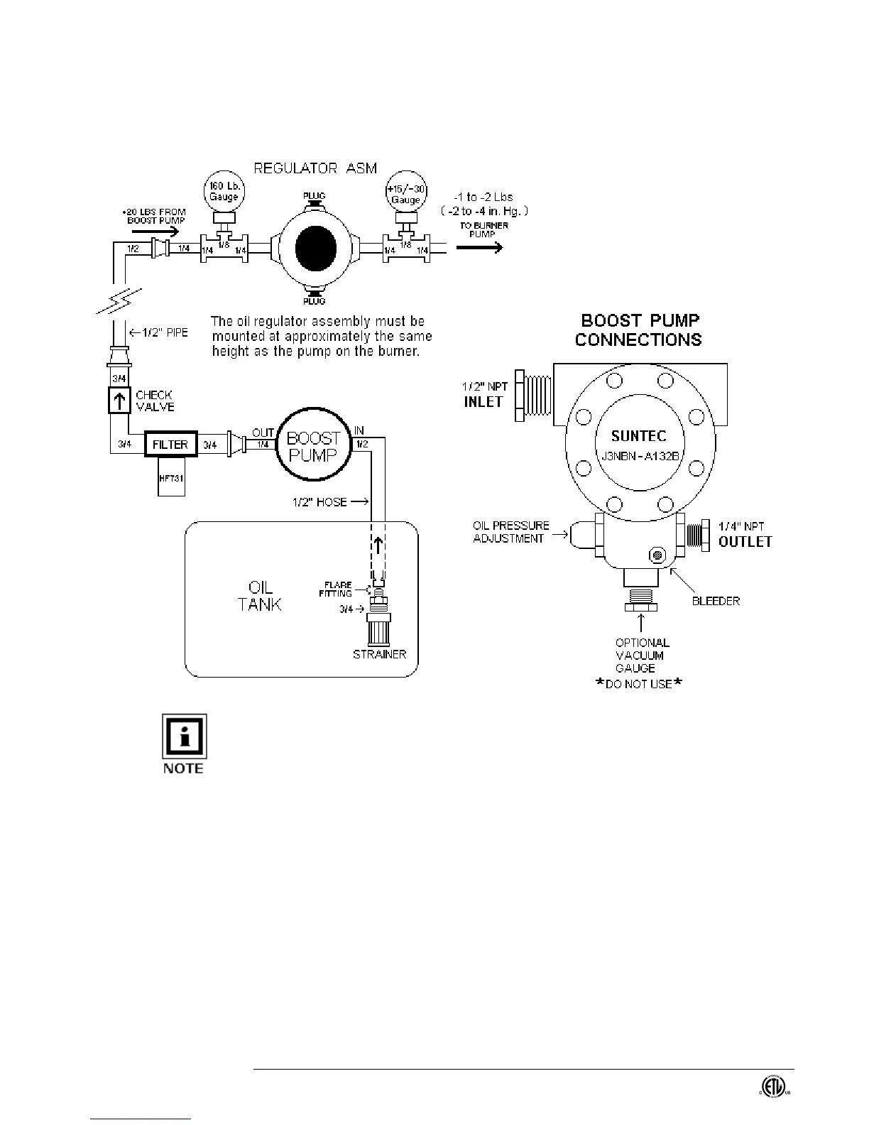
Figure 4 - Diagram Showing Installation of Suntec Boost Pump, Filter, Check valve,
Regulator & Gauges
NOTE: The boost pump can be mounted at or below the level of the oil tank BUT MUST
NOT be mounted more than four feet above.
ALSO: The (+) (-) gauge on the outlet of the regulator shows positive (+) pressure in
pounds per square inch (PSI) and negative pressure in inches of mercury (in. Hg). One
PSI is equal to two inches of mercury and, with earth’s air pressure being around 15
PSIG at sea level, a reading of –30 inches of mercury is equal to a complete vacuum. A
setting of –4 on this gauge should be adequate. If the pressure falls below –10 there is
an increased chance that you will start sucking air through the pump seal or fail to get
adequate firing pressure due to normal pump wear. Positive pressure on this gauge
means you are shoving oil into the burner pump. The internal regulator in this pump will
regulate properly only when the pump is sucking on the inlet line – so don’t run with a
positive pressure on this gauge. A good rule of thumb for setting the pressure is to first
set the regulating screw in the burner pump at mid range and then adjust the external
regulator for a proper flame length. This allows you to make future flame length
adjustments using the burner pump pressure regulator screw – which is the correct
procedure.


 To Next Page