Do you have a question about the Inovance AM403 Series and is the answer not in the manual?
General precautions for safe installation, usage, and maintenance of the PLC.
Defines warning and caution symbols and their meanings for user safety.
Safety considerations and requirements for designing control systems with the PLC.
Safety precautions and procedures for installing the PLC module.
Safety guidelines and precautions for wiring the PLC and its components.
Guidelines for disposing of the PLC module as industrial waste according to regulations.
Details the model number structure and identifies key information on the PLC nameplate.
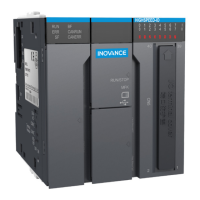
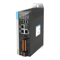
Describes the various external ports and connectors on the CPU module.
Lists the general technical specifications of the PLC module.
Illustrates the terminal layout of the CPU module and pin assignments.
Provides important precautions and considerations for wiring the high-speed I/O.
Displays the physical dimensions of the CPU module in millimeters.
Details the RJ45 cable connection for communication modules.
Explains the specifications and connection for the EtherCAT bus.
Describes the networking and connection for CANopen/CANlink communication.
Details the RS485 serial communication port and its connection.
Explains how to establish an Ethernet connection for monitoring the PLC.
Information on how to download the InoProShop programming software.
Hardware and software requirements for setting up the programming environment.
Procedure for starting and stopping the PLC system.
Explains the functions of the RUN, ERR, SF, and BF indicators.
Describes the usage of the MFK key, including IP address reset.
Explains the LED display for fault codes and system status.
Instructions for connecting power supply, CPU, and expansion modules.
| Digital Inputs | 16 |
|---|---|
| Digital Outputs | 16 |
| Analog Inputs | 4 |
| Analog Outputs | 2 |
| Power Supply | 24 VDC |
| Category | Controller |
| CPU Type | 32-bit |
| Communication Ports | Ethernet, RS485 |


