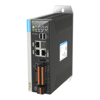
Do you have a question about the Inovance AM300 Series and is the answer not in the manual?
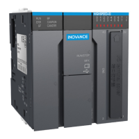
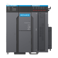
Describes the AM300 PLC's features including dual-Ethernet, FB/FC technology, and expansion capabilities.
Lists product certifications, directives, and standards compliance, referring to nameplate details.
Lists related documents like User Guide, Programming Guide, and Instruction Guide with data codes.
Tracks document revisions with dates and versions, such as "July 2023" and "June 2023".
Explains how to obtain the PDF version of the guide via website or QR code.
Essential safety instructions for equipment use, compliance risks, and environmental requirements for safe operation.
Defines DANGER, WARNING, and CAUTION levels used in the guide for safety notices and their implications.
Cautions for handling equipment during transportation and storage, covering environmental factors and packaging.
Safety advice for installing equipment, emphasizing professional execution and avoiding specific environmental conditions.
Critical safety warnings and practices for electrical wiring, grounding, and handling live circuits.
DANGER and WARNING notices for power-on, including pre-checks and post-power-on actions to prevent hazards.
DANGER warnings that operation must be by professionals and not touching terminals during operation.
DANGER and WARNINGs related to maintenance, emphasizing power off, terminal safety, and routine inspections.
DANGER and WARNINGs for repair, including power off, fuse trips, handling faulty equipment, and part replacement.
Describes the meaning of safety labels on the equipment for safe operation and maintenance.
Explains the model designation (AM320-0808TN) and details of the product nameplate for identification.
Lists general specifications like program capacity, data capacity, EtherCAT, axis control, and expansion capabilities.
Details rated input voltage, current, output voltage/current, protection, and hot swap capabilities.
Specifies input type, channels, mode, voltage, current, response time, frequency, impedance, and filter settings.
Details output type, channels, load ratings, response time, frequency, leakage, residual voltage, and protection.
Specifies operating environment, altitude, pollution degree, immunity, EMC, vibration, shock, and temperature/humidity requirements.
Details installation directions, input/output derating based on ambient temperature for horizontal mounting.
Recommends optimal horizontal mounting for heat dissipation and specifies minimum clearance requirements.
Provides detailed mounting dimensions in mm, including DIN rail position and required hook space.
Step-by-step guide on how to mount the PLC onto a DIN rail, including locking the mounting hook securely.
Instructions on how to install expansion modules and end plates onto the PLC or other modules.
Steps to safely remove the PLC from the DIN rail using a tool, by releasing the mounting hook.
Shows the terminal layout of the PLC, mapping input/output signals and power terminals to their respective connectors.
Explains how to wire sink input signals to the PLC, including internal circuit diagram and signal wiring.
Explains how to wire source input signals to the PLC, including internal circuit diagram and signal wiring.
Shows how the PLC connects to other devices and systems via Ethernet, RS485, and RS232 communication ports.
Provides a table for selecting appropriate cable lugs and cable diameters for various AWG sizes.
Details terminal definitions and wiring for RS485 communication, including bus topology and termination.
Instructions for connecting Ethernet cables, including type of cable required and connection method for reliability.
Steps for starting and stopping the PLC, including checking RUN indicator status for operational feedback.
Procedure for burning a user program onto an SD card and loading it into the PLC, including safety advice.
Steps for upgrading PLC firmware using an SD card, including indicator status for progress and success.
| Series | AM300 |
|---|---|
| Category | Controller |
| Operating Voltage | 24 VDC |
| Output Voltage | 24 VDC |
| Control Mode | Position, Speed, Torque |
| Storage Temperature | -20°C to 70°C |
| Communication | CANopen, EtherCAT |
| Programming Language | IEC 61131-3 (LD, ST, FBD, SFC) |
| Input Voltage | 24V DC |
| Output Current | Varies by model |
| Power Rating | Varies by model |
| Protection Features | Overcurrent, Overtemperature, Overvoltage |
| Humidity | 5% to 95% (non-condensing) |
| Dimensions | Varies by model |
| Weight | Varies by model |


