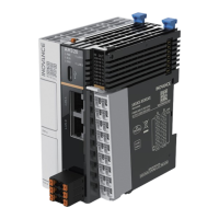
Do you have a question about the Inovance AC700 Series and is the answer not in the manual?
Introduces the AC700 series controller and the purpose of the user guide.
Lists related documents for the AC700 series, including PLC programming software.
Records changes made to the document across different versions.
Provides instructions on how to download the electronic PDF version of the guide.
Outlines the disclaimer regarding safety instructions and Inovance's responsibility.
Defines safety levels (Danger, Warning, Caution) and their implications.
Provides general safety precautions related to product appearance and drawings.
Details steps for unpacking and accepting the product, with warnings and cautions.
Covers safety precautions for installing the controller, including dangers and warnings.
Details safety precautions for wiring the controller, including dangers and warnings.
Provides safety precautions for operating the controller, including dangers and warnings.
Lists safety precautions for maintenance and repair operations, including dangers and warnings.
Provides guidelines for safe disposal and explains safety signs displayed on the equipment.
Describes the product's nameplate and the components of its model number.
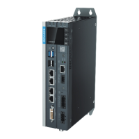
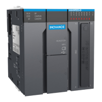
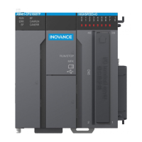
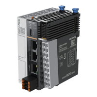
Lists AC700 series models, their specifications, and introduces external ports.
Details the numbered ports on the AC700 controller and their functions.
Provides a comparative table of basic specifications for AC702 and AC703 models.
Lists environmental parameters and their specifications for working, transportation, and storage.
Details the electromagnetic compatibility (EMC) specifications for the AC700 series controller.
Outlines requirements and precautions for installing the controller.
Shows the physical dimensions required for installing the AC700 controller.
Describes the method for installing the controller using screws through the rear earhook.
Provides suggestions for grounding the controller and its shielded cables.
Details cable requirements and recommends noise filter installation for interference suppression.
Explains the power input terminal definition and input power supply specifications.
Introduces the I/O communication port and its connector type.
Details the I/O communication port pin assignments and functions.
Lists specifications for high-speed digital input ports.
Lists specifications for digital output, RS485, and RS232 communication ports.
Explains wiring for power-on and run/stop signal terminals.
Provides instructions for wiring the RS485 bus, including topology and termination.
Describes multi-node topologies for RS485 bus, including daisy chain and star connection.
Details terminal wiring for RS485 and instructions for RS232 bus wiring.
Introduces network ports and their functions.
Explains Ethernet connection methods and details network port indicators.
Provides instructions and indicator details for Ethernet connections.
Details EtherCAT specifications and wiring requirements.
Lists specifications for shielded twisted pair Cat 5e or above cables for EtherCAT.
Details Ethernet signal pins and describes the specifications and pin definitions of the display port.
Lists USB port specifications and covers cable selection criteria and preparation for pin terminals.
Details preparation procedures for cables with cord end terminals and for the I/O connector.
Explains power-on safety precautions and the PLC startup process with different IP settings.
Covers power-off safety precautions and operations during power failure.
Describes controller behavior during instantaneous power-offs and operations after power-off judgment.
Shows the controller's display and describes the content displayed.
Explains the functions and remarks for various indicators on the controller display.
Guides users on how to obtain the InoProShop software and related documents.
Details PC requirements and connection method for installing the programming software.
Provides a step-by-step guide for installing the InoProShop software, including screenshots.
Continues the installation procedure for selecting components and program folders.
Completes the software installation procedure and explains how to set the language.
Instructs on how to change the user interface language of the InoProShop software.
Outlines periodical inspection requirements for power supply and environment conditions.
Covers maintenance checks for wiring and battery installation/removal precautions.
Provides precautions and steps for installing and removing the controller's battery.
Explains the purpose of battery installation and the battery life and replacement interval.
Details procedures and precautions for upgrading PLC firmware and user programs using a USB flash disk.
Explains how to restore default IP addresses and obtain the controller's IP address using a USB flash disk.
Lists BIOS process codes and their descriptions during controller startup.
Lists BIOS error codes and their descriptions for the controller.
Details FPGA error codes and runtime error codes for Modbus RTU, Modbus TCP, and CPU errors.
Lists EtherCAT error codes and their descriptions, starting with 'E'.
Continues the list of EtherCAT error codes and their descriptions.
| Category | Controller |
|---|---|
| Model | AC700 Series |
| Communication | RS-485, Ethernet |
| Encoder Type | Incremental, Absolute |
| Operating Temperature | -10°C to +60°C |
