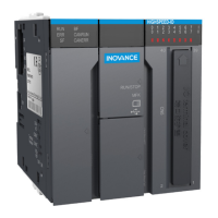
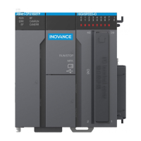
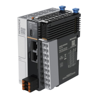
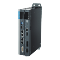
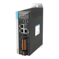
Do you have a question about the Inovance AM500 Series and is the answer not in the manual?
Overview of AM500 PLC features, EtherCAT, and expansion modules.
Lists product certifications, directives, and applicable standards.
Essential safety instructions for proper equipment use.
Defines DANGER, WARNING, and CAUTION safety levels.
Important warnings to follow during product unpacking.
Cautions to observe when unpacking the equipment.
Handling precautions during transportation and storage.
Safety warning: operation must be performed only by professionals.
Warnings to follow before and during installation.
Cautions for safe installation procedures.
Critical dangers related to wiring, grounding, and power.
Important warnings for safe and correct wiring practices.
Precautions for ESD and proper cable usage during wiring.
Dangers associated with improper power-on procedures.
Checks required before powering on the equipment.
Dangers related to improper operation.
Precautions for safe operation of the equipment.
Dangers during maintenance, especially with power ON.
Recommendations for routine and periodic maintenance.
Dangers during repair, especially with power ON.
Procedures and warnings for equipment repair.
Warnings regarding improper disposal of equipment.
Details model naming conventions and nameplate information.
Description of indicator lights and DIP switch functions.
Explanation of various terminal types and their functions.
Covers capacity, axes, programming platform, and more.
Specifications for EtherCAT, Ethernet, RS485, and USB communication.
Specifications for pulse inputs and outputs.
Methods for uploading user programs via Ethernet, TF card, or Type-C.
Details on rated input voltage, current, and protection.
Technical specifications for digital inputs.
Technical specifications for transistor outputs.
Requirements for the operating environment and immunity.
Specifies operating temperature and humidity limits.
Details on mounting options and clearances.
Recommended horizontal mounting and ventilation clearances.
Describes alternative mounting configurations.
Derating limits based on installation orientation.
Keep product away from high-temperature heat sources.
General precautions to follow during installation.
Ensure power is OFF before installing or removing modules.
Physical dimensions and mounting hole specifications.
Step-by-step guide for mounting the PLC onto a DIN rail.
Care instructions for the PLC's mounting hook.
Procedure for adding expansion modules.
Instructions for detaching the PLC from the DIN rail.
Maintenance of the mounting hook when the PLC is not on the rail.
Diagram and table showing terminal assignments.
Guidelines for high-speed I/O extension cable length and routing.
Wiring diagrams for sink input types.
Wiring diagrams for source input types.
Wiring diagrams for output terminals.
Overview of communication capabilities and connections.
Guidance on choosing appropriate cables for communication.
Procedures for connecting RS485 and Ethernet cables.
Specifics on connecting RS485 communication ports.
Specifics on connecting Ethernet communication ports.
Detailed specifications for EtherCAT protocol.
Requirements for EtherCAT communication cables.
Cable specifications and continuity tests for EtherCAT.
Details on RS485 bus topology and connection.
Procedures for starting and stopping the PLC.
Steps to burn a user program using an SD card.
Steps to upgrade PLC firmware using an SD card.
| Category | Controller |
|---|---|
| Series | AM500 |
| Power Supply | 24V DC |
| Programming language | IEC 61131-3 (LD, FBD, IL, SFC, ST) |
| Communication | EtherCAT, CANopen |
| I/O | Expandable I/O modules |
| Communication Ports | Ethernet |
| Operating Temperature | 0°C to 55°C |
| Digital Inputs | Varies depending on the base unit and I/O modules |
| Digital Outputs | Varies depending on the base unit and I/O modules |


