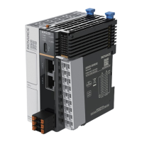
Wiring
-20-
Definition of the I/O communication port
Type
Function
Terminal
No.
I/O communication
port
No.
Terminal
Function
Type
RS485
RS485+ 485+ 1
2 232R RS232
receiving
RS232
RS485– 485– 3 4 232T RS232
transmit-
ting
Serial port
ground
GND 5 6 GND
Serial port
ground
DI Power-on
signal
7 8
RUN/STOP
DI
DI
High-speed
input 0
X0 9 10 X1
High-speed
input 1
DI
DI
High-speed
input 2
X2 11 12 X3
High-speed
input 3
DI
DI
High-speed
input 4
X4 13 14 X5
High-speed
input 5
DI
DI
High-speed
input 6
X6 15 16 X7
High-speed
input 7
DI
DI Input
common
terminal
S/S
17 18 COM Output
common
terminal
DO
DO
High-speed
output 0
Y0 19 20 Y1
High-speed
output 1
DO
DO
High-speed
output 2
Y2 21 22 Y3
High-speed
output 3
DO
Note
When the PLC crashes, you can forcibly stop and restart the PLC program through the RUN/STOP port.
To do so, you need to connect the RUN/STOP port to 24 V and the S/S port to 0 V. Then, the startup icon on the dis-
play turns off, indicating that the PLC is forcibly stopped.
4.3.2 Port Specifications
High-speed digital input specifications (pins 9/10/11/12/13/14/15/16)
Item
Specifications
Number of channels
8
Input type
DC digital input
Input mode SINK/SOURCE
Max. input frequency 200 kHz
Frequency detection error ±1 pulse
Input impedance 4.3 kΩ
Input voltage/current class
Detection voltage: 24 V (Max.: 30 V. When all inputs are ON, the input
voltage does not exceed 26.4 V.)
ON: Voltage ≥ 15 V; Input current > 5 mA
OFF: Voltage ≤ 5 V; Input current < 1.5 mA
 Loading...
