3. Electrical Installation
- 74 -
3
Ɣ
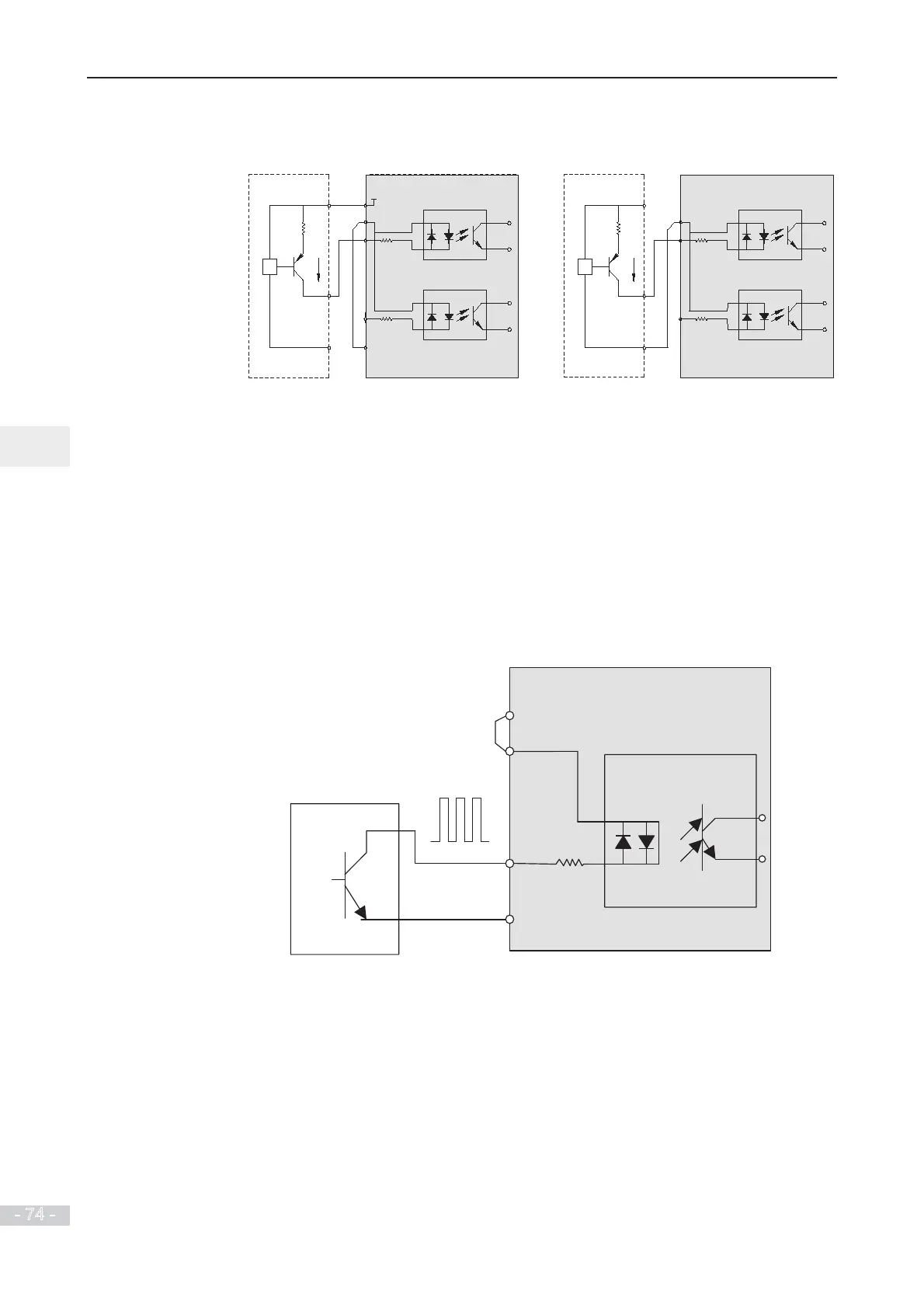
Source wiring
Figure 3-23 Wiring in SOURCE mode
0
V
DI5
DI1
OP
+24V
PNP
Signal
Internal 24 V power supply is applied.
MD290 drive
control board
+VCC
COM
0V
DI5
DI1
OP
PNP
Signal
External
controller
+24V
External 24 V power supply is applied.
MD290 drive
control board
External
controller
If you intend to use internal power supply of the drive, remove the jumper between
terminals +24V and OP. Connect +24V to the common port of external controller, and
connect terminal OP to terminal COM.
If you intend to use an external power supply, remove the jumper between terminals
+24V and OP. Connect external power 0V to terminal OP, and the positive side of
external power +24V to corresponding DI terminal via contact on external controller.
Ƶ
Wiring of DI5 (High-speed Pulse Input)
As high speed pulse input terminal, DI5 allows maximum frequency input of 100 kHz.
Figure 3-24 Wiring of high-speed pulse input terminal
COM
Pulse output device
MD290
+24V
OP
DI5
 Loading...
