3. Electrical Installation
- 48 -
3
Chapter 3 Electrical Installation
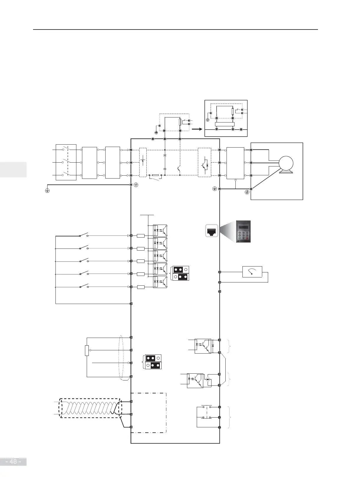
3.1 Typical System Connection
R
S
U
V
W
+24Vdc
DI1
DI2
DI3
DI4
DI5
COM
+10V
AI2
GND
485+
485-
GND
AI1
T/C
T/B
T/A
FM
COM
DO1
CME
AO1
GND
L1
L2
L3
-
+
BR
-+
BR
Jumper J9 for AI2
Forward run
F4-00 = 1
Forward jog
F4-01 = 4
Fault reset F4-02 = 9
Reference 1
F4-03 = 12
Reference 2
F4-04 = 13
The DI5 supports a maximum of 100
kHz pulse input.
VR
1 to 5 kȎ
0 to 10 V
0 to 10 VDC or
0 to 20 mA
MD38TX1
(option)
J13
extension
port
Analog output
(voltage/current switchable)
0 to 10VDC/ 0 to 20mA
Pulse output: 0 to 100 kHz
Open-collector output:
10 to 24VDC/ 0 to 50mA
Open-collector output:
10 to 24VDC/ 0 to 50mA
Relay output:
250 VAC, between 10 mA and 3 A
30 VDC, between 10 mA and 1 A
Braking unit
Mains
External RFI
filter
Line reactor
(option)
Supply ground
RS485+
RS485
-
Current mode
Voltage mode
Current mode
Voltage mode
Jumper J7 for AO1
0 100%
RJ45
Hot pluggable
Remote Keypad
Output
reactor
(option)
IM
The drive of 18.5 to 75kW with
GB or 22 to 90kW with ‘PB’
has built-in braking unit.
The drive of 90G/110P or larger power requires
an optional external dynamic braking unit.
A braking resistor with temperature switch
 Loading...
