3. Electrical Installation
- 77 -
3
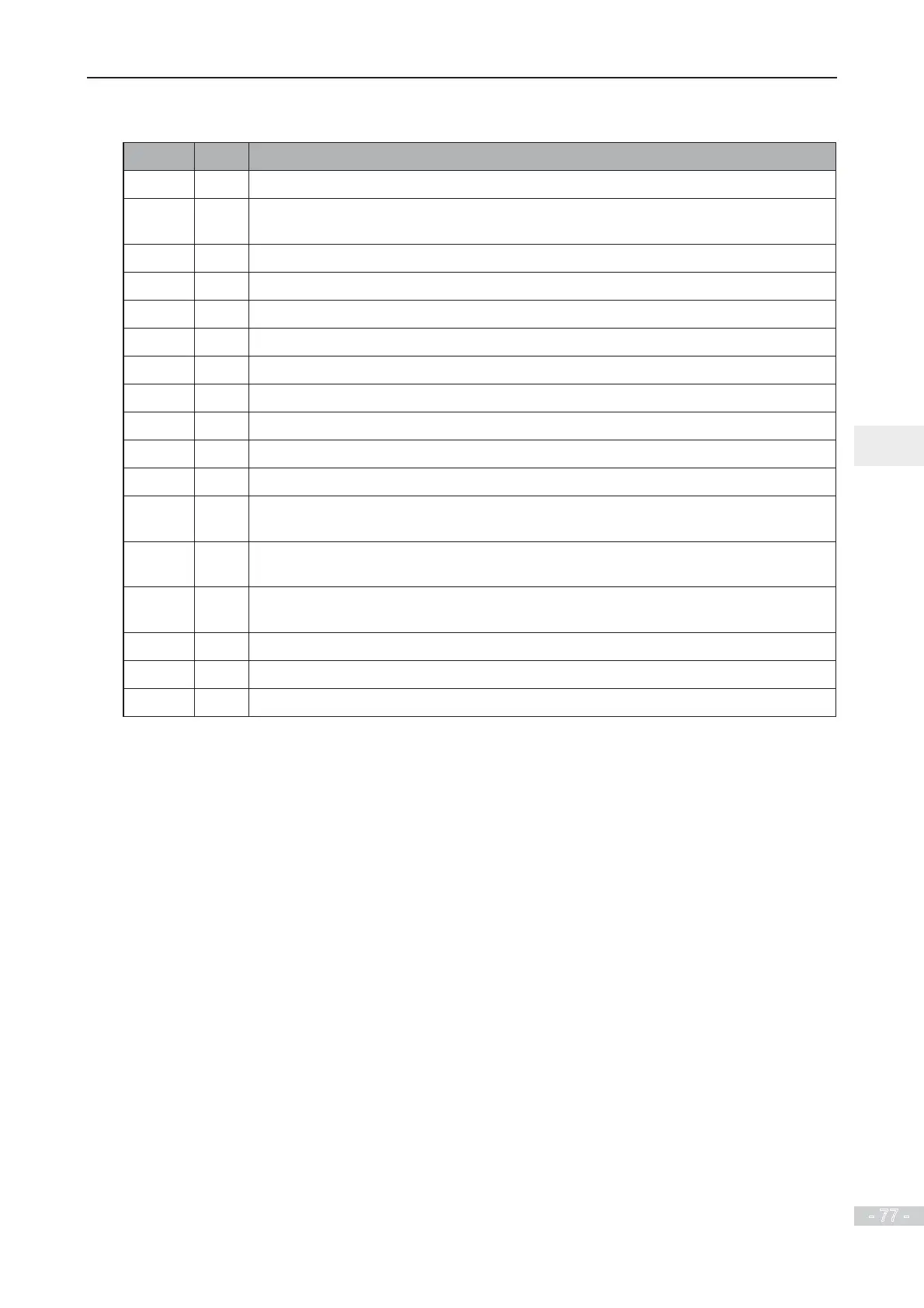
3.4 Wiring Checklist
Ƒ¥ No. Item
Ƒ 1 Check that you receive a correct model .
Ƒ 2 (QVXUHFRUUHFWSHULSKHUDOGHYLFHVEUDNLQJUHVLVWRUEUDNLQJXQLW$&UHDFWRU¿OWHUDQG
breaker) are used.
Ƒ 3 Check optional cards to ensure the receiving is correct.
Ƒ 4 Check that mounting method and location meet the requirements.
Ƒ 5 &KHFNSRZHUVXSSO\LQSXWLVZLWKLQVSHFL¿FDWLRQHJ9$&
Ƒ 6 &KHFNWKDWUDWHGPRWRUYROWDJHPDWFKHVWKHGULYHRXWSXWVSHFL¿FDWLRQ
Ƒ 7 Connect power supply to the R, S, T terminals of the drive properly.
Ƒ 8 Connect motor input cables to the U, V, W terminals of the drive properly.
Ƒ 9 &KHFNWKDWFDEOHGLDPHWHURIPDLQFLUFXLWFRPSOLHVZLWKVSHFL¿FDWLRQ
Ƒ 10 Decrease F0-15 (carrier frequency) if motor output cable exceeds 50 m.
Ƒ 11 Ground the AC drive properly.
Ƒ 12 Check that output terminals and control signal terminals are connected securely and
reliably.
Ƒ 13 Check whether more than one motors are driven. If yes, consider whether to add a
thermal relay.
Ƒ 14 When using braking resistor and braking unit, check whether they are wired properly
and whether their resistance value is proper.
Ƒ 15 Use shielded twisted pair (STP) cables as signal lines.
Ƒ 16 Connect optional cards correctly.
Ƒ 17 Segregate control wiring from power supply and motor cables.
 Loading...
