MD380 User Manual Desc
ription of Function Codes
- 169 -
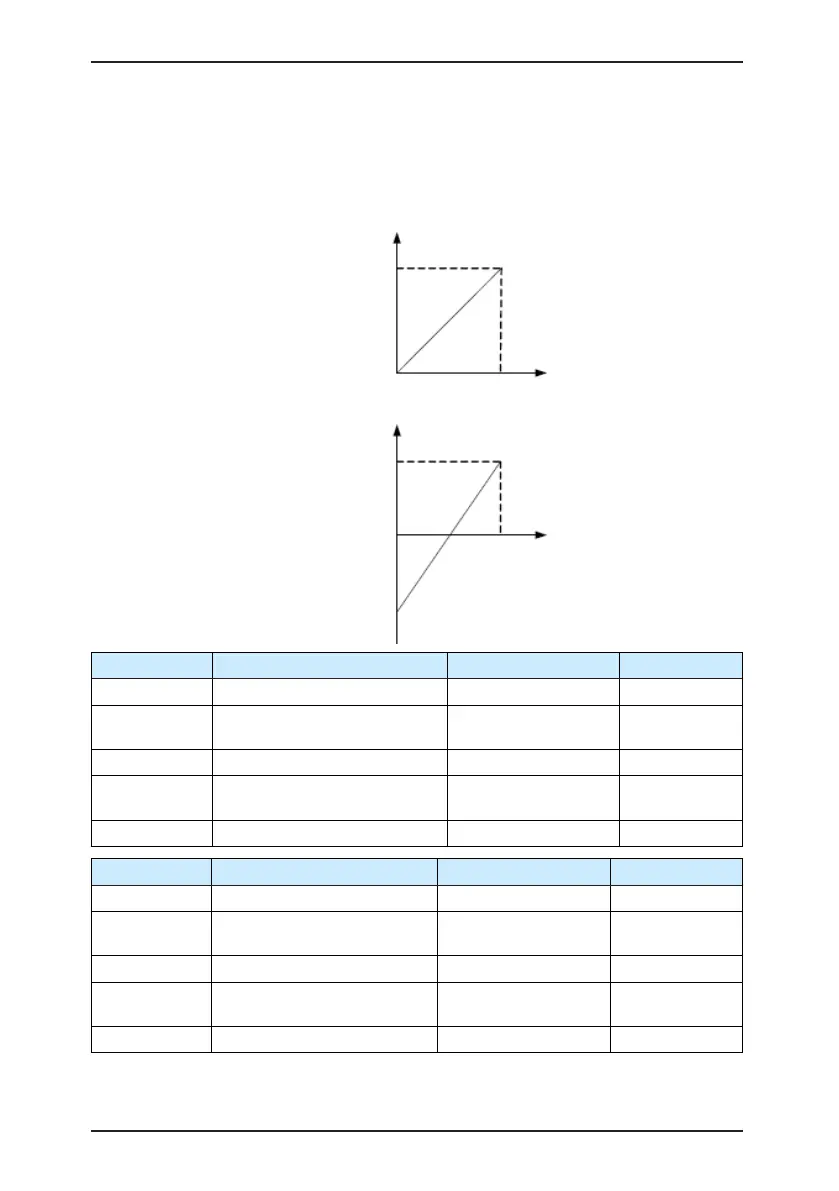
In different applications, 100% of analog input corresponds to different nominal values. For
details, refer to the description of different applications.
Two typical setting examples are shown in the following gure.
Figure 6-11 Corresponding relationship between analog input and set values
Corresponding set value
(frequency, torque)
100.0%
0 V (0 mA)
10 V (20 mA)
AI
Corresponding set value
(frequency, torque)
100.0%
0 V (0 mA)
10 V (20 mA)
AI
-100.0%
Function Code Parameter Name Setting Range Default
F4-18 AI curve 2 minimum input 0.00 V to F4-20 0.00 V
F4-19
Corresponding setting of AI
curve 2 minimum input
-100.00%–100.0% 0.0%
F4-20 AI curve 2 maximum input F4-18 to 10.00 V 10.00 V
F4-21
Corresponding setting of AI
curve 2 maximum input
-100.00%–100.0% 100.0%
F4-22 AI2 lter time 0.00–10.00s 0.10s
Function Code Parameter Name Setting Range Default
F4-23 AI curve 3 minimum input 0.00 V to F4-25 0.00 V
F4-24
Corresponding setting of AI
curve 3 minimum input
-100.00%–100.0% 0.0%
F4-25 AI curve 3 maximum input F4-23 to 10.00 V 10.00 V
F4-26
Corresponding setting of AI
curve 3 maximum input
-100.00%–100.0% 100.0%
F4-27 AI3 lter time 0.00–10.00s 0.10s
The method of setting AI2 and AI3 functions is similar to that of setting AI1 function.

 Loading...
