2 Installation and Setting
- 5 -
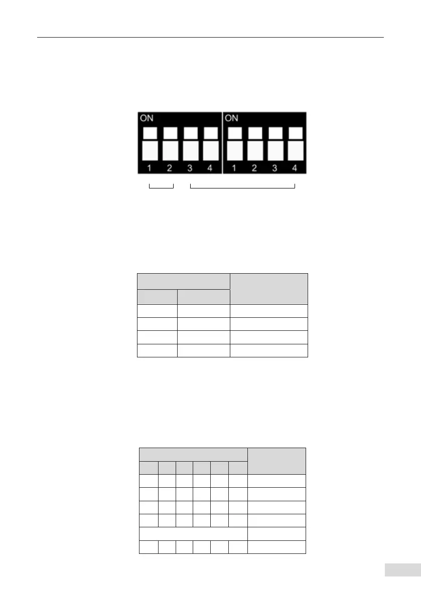
The DIP switches S2 and S3 compose an 8-digit DIP switch for setting the baud rate and
device address for CAN bus communication. The following gure shows the numbering
of DIP switches. Switches 1 and 2 are used to set the baud rate, and switches 3 to 8 are
used to set the CANopen device addresses. The switch on the ON position indicates 1,
and indicates 0 otherwise.
1 2 3 4 5 6 87
Baud rate
CANopen device address
Figure 2-4 Numbering of MD38CAN2 DIP switches
■
Baud rate
The following table describes the relationship between the DIP switch states and the
baud rates.
Table 2-4 Setting the baud rate for MD38CAN2
DIP Switch No.
Baud Rate
1 2
0 0 125 Kbps
0 1 250 Kbps
1 0 500 Kbps
1 1 1 Mbps
■
CANopen device address
MD38CAN2 provides six switches for setting the CANopen device addresses. Switch 3 is
the highest bit, and switch 8 is the lowest bit. Switches 3 to 8 correspond to b5 to b0 of a
16-bit binary integer. The address range to be set is 1–63, as listed in the following table.
Address 0 is reserved and cannot be used. If you set address 0, MD38CAN2 will not work.
Table 2-5 Addresses set by the DIP switches of the MD38CAN2
DIP Switch No.
Address
3 4 5 6 7 8
0 0 0 0 0 0 Reserved
0 0 0 0 0 1 1
0 0 0 0 1 0 2
0 0 0 0 1 1 3
…… …
1 1 1 1 1 1 63
 Loading...