7. Interfaces and Communication
- 204 -
F5-07 and F5-08 define how AO terminals indicate the drive internal running parameters in
analog mode.
It is possible to change sense, offset and scaling of parameters on analog outputs. This is by
correcting outputs according to the following formula:
Y = kX + b,
Where:
● Y = output parameter after correction.
● X = output parameter before correction.
● k = scaling factor set by F5-11.
● b = offset set by F5-10.
Note that scaling and offset values can be positive or negative.
■
Use of PG Terminal
The FVC mode with sensor, set by function code F0-01 = 1, helps to improve stability and
accuracy of motor speed control. In this case it is necessary to install an encoder on motor to
provide sensor input to PG card that the drive requires.
There are four versions of PG card to support different encoder types:
● Differential encoder
● UVW encoder and wire-saving UVW encoder
● Resolver
● Open-collector encoder
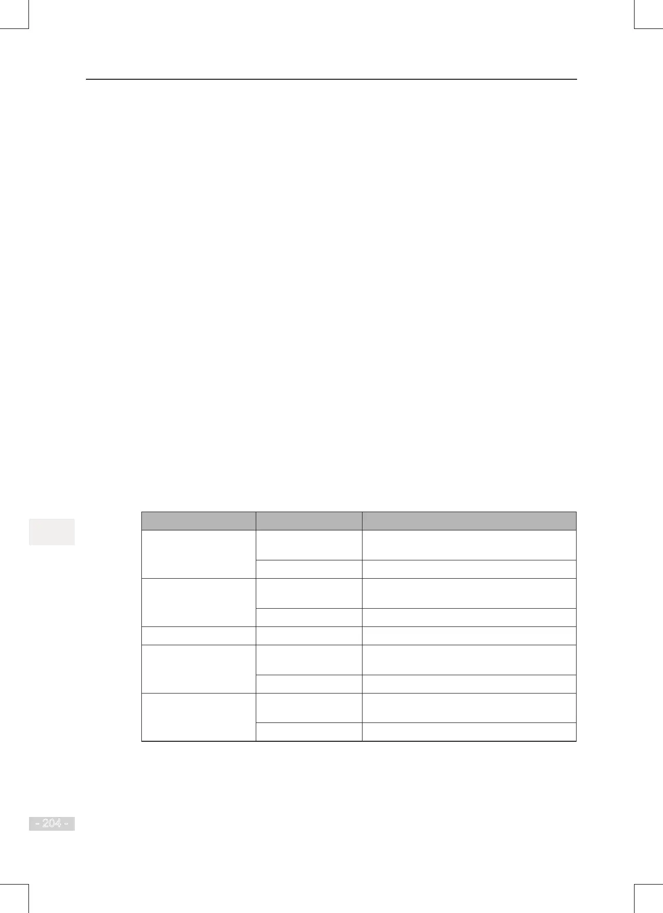
Settings of encoder parameters F1-27 and F1-28 depend on type of encoder used with the drive.
The following table describes function code settings for each of encoder types.
Encoder Type Function Code Description
Differential encoder F1-27 Set to the number of pulses for each motor
revolution.
F1-28 = 0 ABZ incremental encoder
UVW encoder F1-27 Set to the number of pulses for each motor
revolution.
F1-28 = 1 UVW incremental encoder.
Resolver F1-28 = 2 Resolver
Open-collector encoder F1-27 Set to the number of pulses for each motor
revolution.
F1-28 = 0 ABZ incremental encoder.
Wire-saving UVW
encoder
F1-27 Set to the number of pulses for each motor
revolution.
F1-28 = 4 Wire-saving UVW encoder.
 Loading...