Advanced Operations
En-77
Note
• Only analog, NET or USB input source is output from the
ZONE 2/ZONE 3 PRE/LINE OUT jacks and ZONE 2 L/R
terminals.
• You cannot select different AM or FM radio stations for your
main room and Zone 2/3. The same AM/FM radio station
will be heard in each room. Namely, if you have selected an
FM station for the main room, that station will also be output
in Zone 2/3.
• You cannot select different input selector NET or USB for
your main room and Zone 2/3. Namely, if you have selected
USB input selector for Zone 2/3, USB input selector will be
selected in main room even if NET has been selected for
main room.
•“BLUETOOTH” cannot be selected as input selector in
Multi Zone. If you play audio from Bluetooth-enabled device
in Multi Zone, select “Z2 Sel: Source” or “Z3 Sel: Source”,
and “BLUETOOTH” as input selector in Main room.
• When Zone 2/3 is activated and its input selector is
selected, the power consumption of standby mode slightly
increases.
• While Zone 2/3 is on, u functions will not work.
• When setting the AV receiver to standby mode while Zone
2/3 is active, the Z2 or Z3 indicator is dimly lit.
• The Zone 2 level, balance, and tone functions have no
effect on the ZONE 2 PRE/LINE OUT jacks when the
“Zone 2 Out” setting is set to “Fixed” (➔ page 69).
• The Zone 3 volume function has no effect on ZONE 3
PRE/LINE OUT when the “Zone 3 Out” setting is set to
“Fixed” (➔ page 69).
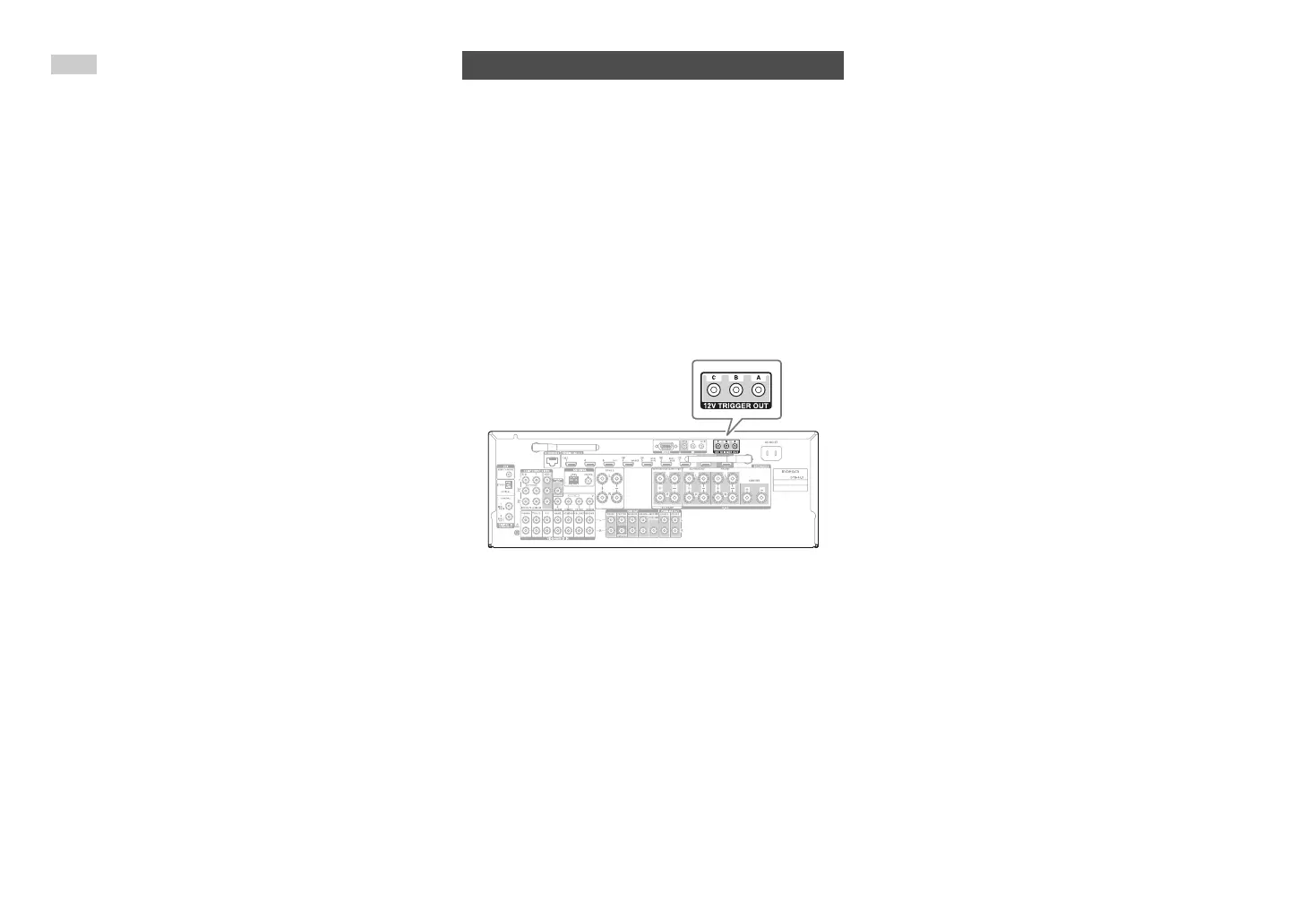
The 12V triggers A, B, and C can be used to turn on
12V trigger-capable components automatically when
they are selected as the input source. The triggers
can be set so that they activate themselves once a
connected component is selected as the input source
for the main room, Zone 2, Zone 3, or any
combination of rooms. When triggered, the output
from a 12V TRIGGER OUT goes high (+12 volts and
150 milliamperes max. at 12V TRIGGER OUT A;
+12 volts and 25 milliamperes max. at 12V TRIGGER
OUT B and C).
See “12V Trigger A/B/C Setup” (➔ page 69).
Hookup
• Use a miniplug cable to connect the AV receiver’s
12V TRIGGER OUT A, B, or C jack to the 12 V
trigger input of a connected component.
Using the 12V Triggers