5
5
4
4
3
3
2
2
1
1
D D
C C
B B
A A
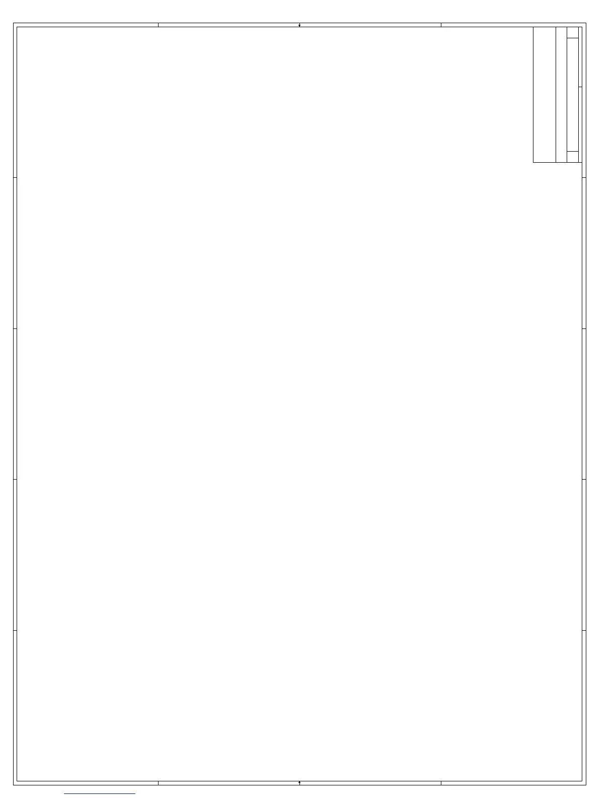
[ ] An 8 layer board, see right for stack up
[ ] The impedance of all signal layers are to be
between 55 and 75 ohms.
[ ] The board impedance should be between 55 and 75
ohms (65 +/- 15%).
[ ] FR-4 material should be used for the board fab.
[ ] The ground plane should not be split.
[ ] If a signal must be routed for a short distance on a
power plane, then use the VCC plane.
[ ] Keep vias for decoupling caps as close to the cap
pads as possible.
Signal (GTL +VTT)
GND
Signal - GTL
Signal
3.3 (most of the board) / GND (Under the S370 + BX)
Signal - GTL
GND
Signal - GTL - VccCore
Use the same stackup thicknesses as baseboard.
Trace Impedance:55 - 75Ohms. (shoot for 65, lower is better than higher!)
Top/bottom layer should be ½ oz cu, inner layers 1 oz cu
[ ] PLL1, PLL2 traces < 0.1 ohm route
8 Layer Board with the following stackup:
Layout guideline checklist
Board
S370_256 Other
[ ] length of HRESET trace from CPU to BX/CPU/ITP node must be between 0.5",1.5"
S370_256 Host Interface
S370_256 Power
[ ] length of HRESET trace from 443BX to BX/CPU/ITP node must be between 0.5",1.5"
[ ] length of trace to 86 ohm must be between 0.5",1.5"
440BX Host Interface
[ ] HRESET# length of trace to 86 ohm must be between 0.5",1.5"
Bus Ratio, Thermal, ITP
[ ] length of HRESET trace from ITP the BX/CPU/ITP node must be between 1.0",3.0"
[ ] Pins AH4,X4 must be daisy chained
[ ] VCC_CORE decoupling -- 4.7uF decoupling capacitors must be place within the socket
cavity and mounted directly on the primary side of the motherboard. The traces must be
as short and wide as possible. Use 1206 package.
[ ] Place DCLKWR cap as close to BX as possible
440BX Memory Interface
GTL Termination
[ ] The trace lengths should be controlled to 1.8" min. and 4.3"
max. from socket370 to BX Chipset
[ ] The stub lengths should be controlled to 0.0" min. to 2.0" max
from socket 370 to R packs.
[ ] The AGTL+ bus trace width is 5 mil. not greater than 6 mils.
[ ] The edge to edge trace spacing is 12 mils. The ratio of this
spacing to the delectric thichness of the layer should be at least
2.
[ ] The minimum spacing can be decreased to 5 mils for escaping
the FCPGA/PPGA areas for a length of less than 0.25"
[ ] The AGTL+ signals should be routed on the signal layer next to
the ground layer (referenced to ground).
[ ] ***** TEST SIGNALS **** Route 3 AGTL+ signals at the
minimum of 1.8" for testing purposes. The 3 signals must be on
the BX side. Use these three signals: BNR#, HD4# HA27#.
[ ] ***** TEST SIGNALS **** Route 5 signals next to each other at
the maximum of 4.3". This is to test crosstalk. The five signals
are: HD29#, HD28#, HD43#, HD37#, HD44#.
[ ] capacitor site on BCLK must be within 0.5" from socket370
Connector
[ ] HCLK0 = HCLK1 - 0.75" in length. IMPORTANT route HCLK0 and HCLK1 on same layer, don't
traverse multiple layers. Place on bottom layer. But keep two signals apart by a spacing of 25
mils. to avoid cross talk.
[ ] G_CLKIN,GCLKO_A+G_CLKOUT, GCLKO_B+G_CLKOUT should all be the
same length
[ ] Route THERMDP & TERMDN as a differential pair
[ ] VREF decoupling -- Intel recommends four or more 0.1uF caps in a 0603 package
placed near VREF pins within 500 mils.
[ ] VREF decoupling --Make MREF short/wide 24 mils minimum
[ ] For VTT decoupling -- place one Cap near every two R-packs in 603
package and place within 200 mils of RPACK.
Silkscreen
[ ] Flexible Intel(R) 440BX AGPset/PGA370 Processor adapter
[ ] Make sure you route the ITP connector right. See page10 for the footprint.
[ ] Number pins on top and bottom of board. Silkscreen.
[ ] Place C86,C87,C88 within 1/2 inch of chip
[ ] Add 4 ground pads below BX in inner ring of balls as shown.
Intel(R) 440BX Scalable Performance Board A3
Layout Guidelines
Embedded Intel Architecture Division
Intel Corporation
5000 W. Chandler Blvd
Chandler AZ, 85044
C
12 12Wednesday, April 26, 2000
Title
Size Document Number Rev
Date: Sheet
of