28 Intel
®
440Bx Scalable Performance Board Development Kit Manual
Hardware Reference
4.2 Post Code Debugger
The evaluation board has an on-board Post Code Debugger. Data from any code that does an I/O
write to 80H is latched on the two led displays (U12/U13). During BIOS startup, code is posted to
these LEDs to indicate what the BIOS is doing. Application code can post its own data to these
LEDs by doing an I/O write to address 80H. The 22V10 PLD code used to implement this function
is included in Appendix A, “PLD Code Listing.”
4.3 ISA and PCI Expansion Slots
The evaluation platform has three PCI expansion slots and two ISA slots.
4.4 PCI Device Mapping
On the evaluation platform the PCI devices are mapped to PCI device numbers by connecting an
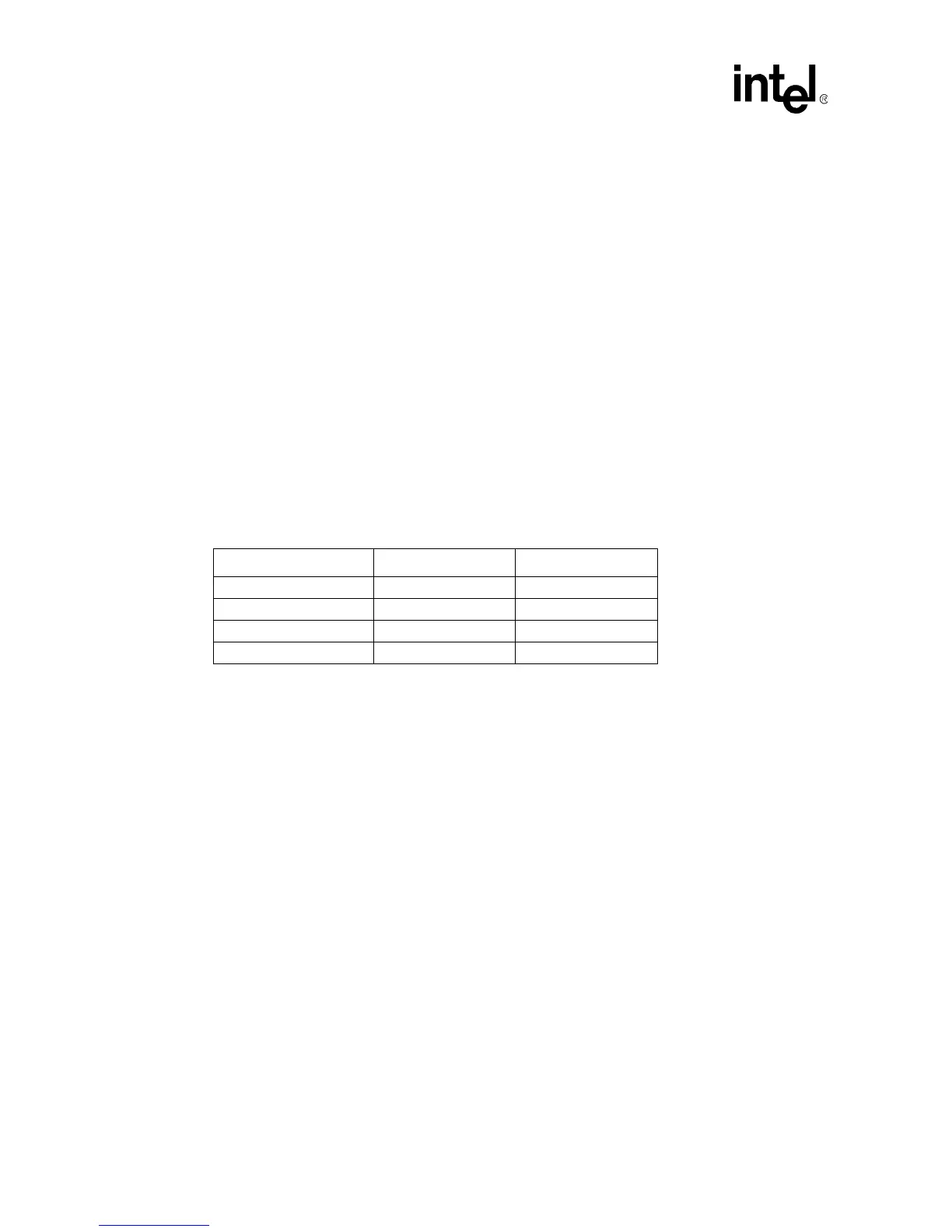
address line to the IDSEL signal of each PCI device. Table 4 shows the mapping of PCI devices.
Table 4. PCI Device Mapping
Device Address Line PCI Device Number
PIIX4E AD18 7
PCI Slot 0 (J7) AD28 17
PCI Slot 1 (J8) AD29 18
PCI Slot 2 (J9) AD30 19