Intel Desktop Board D945GTP Technical Product Specification
64
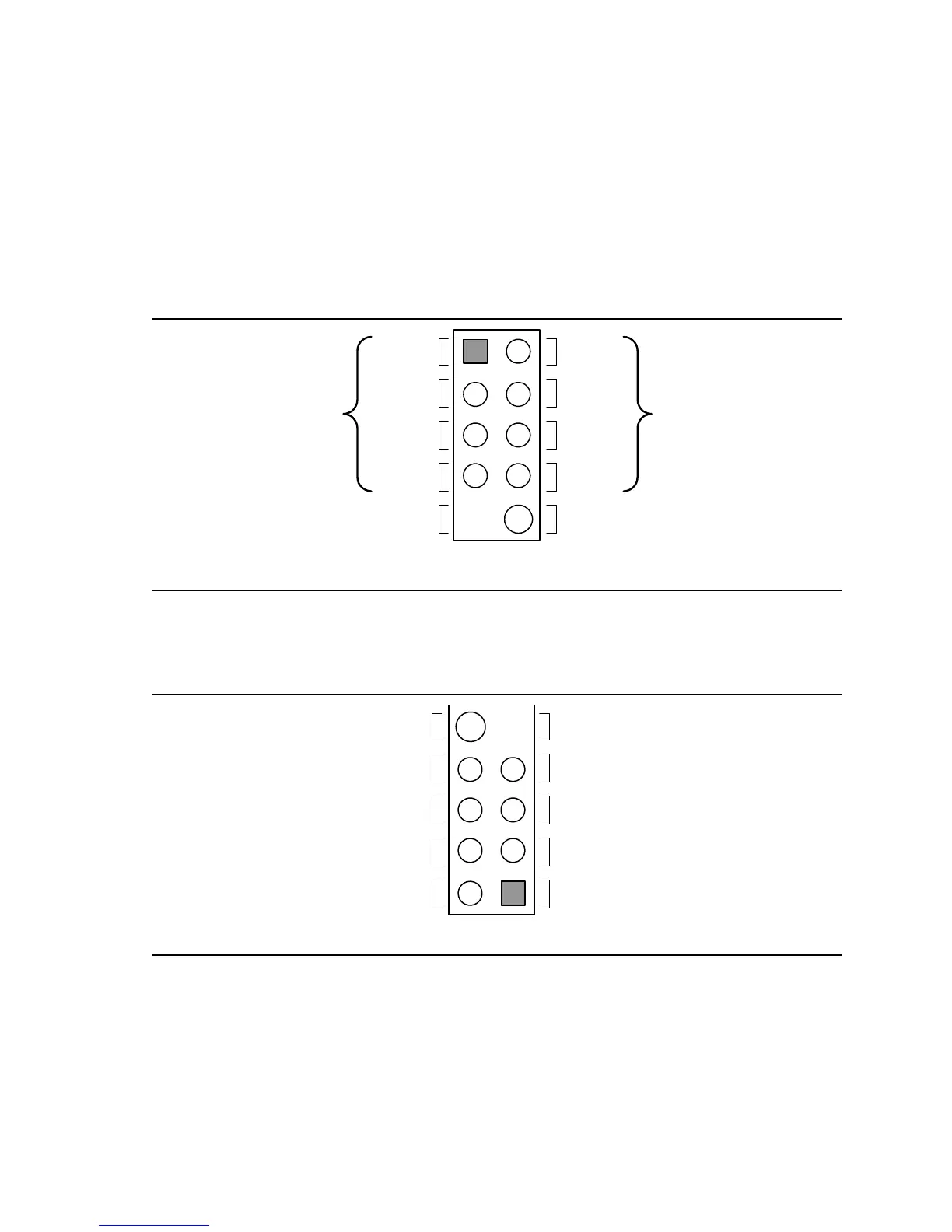
2.8.2.5 Front Panel USB Connectors
Figure 22 is a connection diagram for the front panel USB connectors.
#
INTEGRATOR’S NOTES
• The +5 V DC power on the USB connector is fused.
• Pins 1, 3, 5, and 7 comprise one USB port.
• Pins 2, 4, 6, and 8 comprise one USB port.
• Use only a front panel USB connector that conforms to the USB 2.0 specification for high-
speed USB devices.
OM15963
8
6
4
2
7
5
3
1
Key (no pin)
No Connect
10
Power
(+5 V DC)
D−
D+
Ground
D+
Ground
D−
Power
(+5 V DC)
One
USB
Port
One
USB
Port
Figure 22. Connection Diagram for Front Panel USB Connectors
2.8.2.6 Front Panel IEEE 1394a Connectors (Optional)
Figure 23 is a connection diagram for the optional IEEE 1394a connectors.
OM17834
TPA−
Ground
Ground
Key (no pin)
TPA+
TPB− TPB+
+12 V DC +12 V DC
Ground
8
6
4
2
7
5
3
1
10
Figure 23. Connection Diagram for IEEE 1394a Connectors
#
INTEGRATOR’S NOTES
• The IEEE 1394a connectors are colored blue.
• The +12 V DC power on the IEEE 1394a connectors is fused.
• Each IEEE 1394a connector provides one IEEE 1394a port.