Technical Reference
67
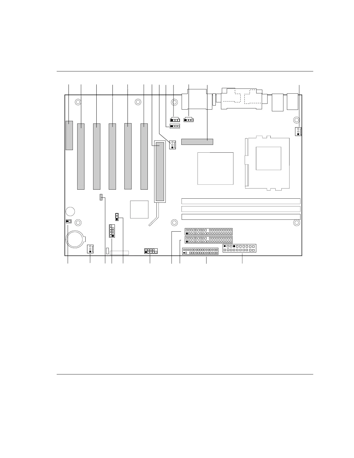
Midboard Connectors
Figure 22 shows the location of the midboard connectors.
KDB C E F G
M
N
A J
HI
L
O
P
Q
RS
TU
V
W
OM10104
1
2
33
34
1
40
39
1
2
40
39
1
2
A CNR (optional) M Processor fan (Fan 3)
B PCI slot 5 N Power
C PCI slot 4 O Diskette drive (Floppy)
D PCI slot 3 P Primary IDE
E PCI slot 2 Q Secondary IDE
F PCI slot 1 R Serial port (COM 2)
G AGP universal S BIOS configuration jumper (see page 38)
H Chassis fan (Fan 2) T USB front panel
I Legacy CD-ROM, white U Wake on LAN technology
J ATAPI-style CD-ROM, black V Chassis fan (Fan 1)
K ATAPI-style auxiliary in, tan W SCSI hard drive activity LED
L Digital Video Output (DVO)
Figure 22. Midboard Connectors