Technical Reference
53
2.8.2 Internal I/O Connectors
The internal I/O connectors are divided into the following functional groups:
• Audio (see page 54)
Auxiliary line in
ATAPI CD-ROM
Legacy style (2-mm) CD-ROM
PC/PCI
• Power and hardware control (see page 56)
Fans (4)
ATX12V
Main power
Auxiliary power
Wake on LAN technology
Wake on ring connector
• Add-in boards and peripheral interfaces (see page 59)
CNR (communication and networking riser)
PCI bus (5)
AGP
IDE (2)
SCSI LED
Diskette drive
2.8.2.1 Expansion Slots
The board has the following expansion slots:
• One Accelerated Graphics Port (ATX Expansion slot 6, J5E1), or AGP50 Graphic Port
(optional).
• Five PCI Local Bus slots (compliant with PCI rev 2.2 specification). The SMBus is routed to
PCI bus connector 2 only (ATX Expansion slot 4, J4B1). PCI add-in cards with SMBus
support can access sensor data and other information residing on the desktop board.
• One CNR (optional), shared with PCI bus connector 5 (ATX Expansion slot 1, J4A1).
✏
NOTE
This document references back-panel slot numbering with respect to processor location on the
board. The AGP slot is not numbered. PCI slots are identified as PCI slot #x, starting with the
slot closest to the processor. The CNR slot shares PCI slot 5.
The ATX/MicroATX specifications identify expansion slot locations with respect to the far edge of
a full-sized ATX chassis. The ATX specification and the board’s silkscreen are opposite and could
cause confusion. The ATX numbering convention is made without respect to slot type (PCI vs.
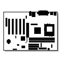
AGP), but refers to an actual slot location on a chassis. Figure 11 on page 59 illustrates the
board’s PCI slot numbering.
 Loading...

