Installing and Replacing Desktop Board Components
49
IEEE 1394a Header
See Figure 22, C for the location of the IEEE 1394a header. Table 8 shows the pin
assignments for the header.
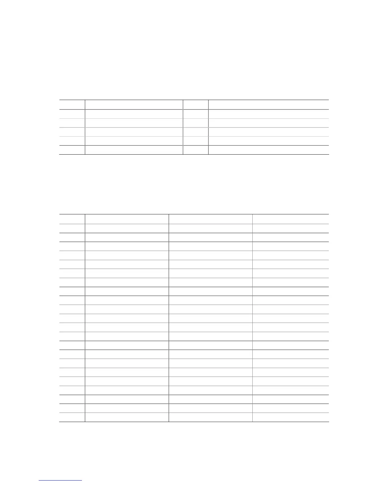
Table 8. IEEE 1394a Header Signal Names
Pin Signal Name Pin Signal Name
1 TPA1+ 2 TPA1-
3 Ground 4 Ground
5 TPA2+ 6 TPA2-
7 +12 V 8 +12 V
9 Key (no pin) 10 Ground
Parallel Port Header
See Figure 22, D for the location of the parallel port header. Table 9 shows the pin
assignments for the header.
Table 9. Parallel Port Header Signal Names
Pin Standard Signal Name ECP Signal Name EPP Signal Name
1 STROBE# STROBE# WRITE#
2 AUTOFD# AUTOFD#, HOSACK DATASTB#
3 PD0 PD0 PD0
4 FAULT# FAULT#, PERIPHREQST# FAULT#
5 PD1 PD1 PD1
6 INT# INT#, REVERSERQST# RESET#
7 PD2 PD2 PD2
8 SLCTIN# SLCTIN# ADDRSTB#
9 PD3 PD3 PD3
10 GROUND GROUND GROUND
11 PD4 PD4 PD4
12 GROUND GROUND GROUND
13 PD5 PD5 PD5
14 GROUND GROUND GROUND
15 PD6 PD6 PD6
16 GROUND GROUND GROUND
17 PD7 PD7 PD7
18 GROUND GROUND GROUND
19 ACK# ACK# INTR
20 GROUND GROUND GROUND
21 BUSY BUSY#, PERIPHACK WAIT#
22 GROUND GROUND GROUND