Intel Desktop Board DG43RK Product Guide
52
Chassis Intrusion Header
Figure 22, I shows the location of the chassis intrusion header. This header can be
connected to a mechanical switch on the chassis to detect if the chassis cover is
removed. Table 14 shows the pin assignments for t
h
e chassis intrusion header.
Table 14. Chassis Intrusion Header Signal Names
Pin Signal Name
1 Ground
2 Intruder#
Connecting to the Audio System
After installing the audio driver, the multi-channel audio feature can be enabled.
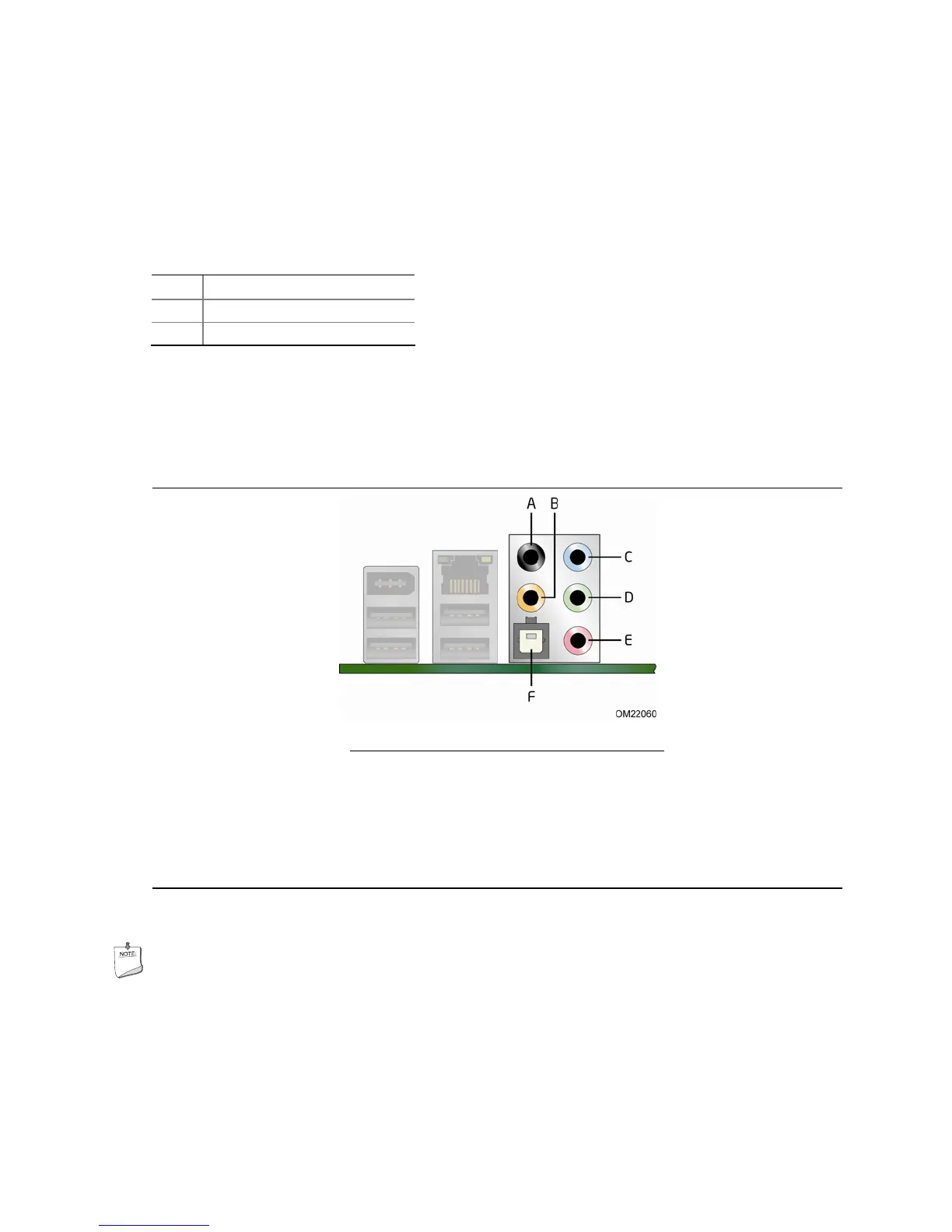
Figure 23 shows the back panel audio connectors.
Item Description
A Rear surround
B Center channel and LFE (subwoofer)
C Line in/Side surround/Headphones
D Front speaker/Headphones
E Mic In
F S/PDIF digital audio out (optical)
Figure 23. Back Panel Audio Connectors
NOTE
The back panel line out connector is designed to power either headphones or amplified
speakers only. Poor audio quality may occur if passive (non-amplified) speakers are
connected to this output.