Installing and Replacing Desktop Board Components
49
Alternate Front Panel Power LED Header
Figure 19, G shows the location of the alternate front panel power LED header. Pins 1
and 3 of this header duplicate the signals on pins 2 and 4 of the front panel header. If
your chassis has a three-pin power LED cable, connect it to this header. Table 11
shows
the pin assignments for the alternate front panel header.
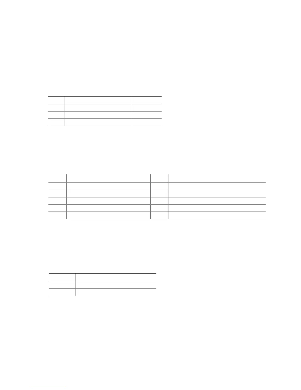
Table 11. Alternate Front Panel Power LED Header Signal Names
Pin Signal Name In/Out
1 Front panel LED+ Out
2 No pin
3 Front panel LED- Out
Serial Header
Figure 19, H shows the location of the serial header. Table 12 shows the pin
assignments and signal names for the serial header.
Table 12. Serial Port Header Signal Names
Pin Signal Name Pin Signal Name
1 DCD (Data Carrier Detect) 2 RXD# (Receive Data)
3 TXD# (Transmit Data) 4 DTR (Data Terminal Ready)
5 Ground 6 DSR (Data Set Ready)
7 RTS (Request To Send) 8 CTS (Clear To Send)
9 RI (Ring Indicator) 10 Key (no pin)
Internal Mono Speaker Header
The internal mono speaker header is shown in Figure 19, J. Table 13 shows the pin
assignments and signal names for the internal mono speaker header.
Table 13. Internal Mono Speaker Header
Signal Names
Pin Signal Name
1 −
2 +