Installing and Replacing Desktop Board Components
47
Table 9. Back Panel CIR Header Emitter (Output) Header Signal Names
Pin Signal Name Pin Signal Name
1 Emitter Out 1 2 Emitter Out 2
3 Ground 4 Key (no pin)
5 Jack Detect 1 6 Jack Detect 2
Chassis Intrusion Header
Figure 23, F shows the location of the chassis intrusion header. This header can be
connected to a mechanical switch on the chassis to detect if the chassis cover is
removed.
Table 10 shows the pin assignments and
signal names for
the chassis intrusion header.
Table 10. Chassis Intrusion Header Signal Names
Pin Description
1 Intruder
2 Ground
Front Panel Header
Figure 23, H shows the location of the front panel header. Table 11 shows the pin
assignments and signal names for the front panel header.
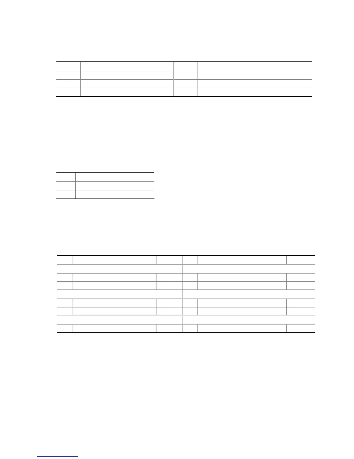
Table 11. Front Panel Header Signal Names
Pin Description In/Out
Pin Description In/Out
Hard Drive Activity LED Power LED
1 Hard disk LED pull-up to +5 V
Out 2 Front panel green LED Out
3 Hard disk active LED Out 4 Front panel yellow LED Out
Reset Switch On/Off Switch
5 Ground 6 Power switch In
7 Reset switch In 8 Ground
Power Not Connected
9 Power Out 10 No pin
 Loading...