Installing and Replacing Desktop Board Components
39
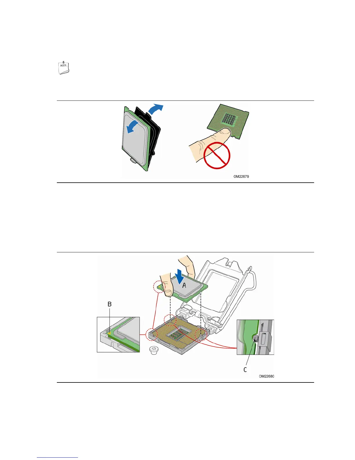
4. Remove the processor from its protective cover. Hold the processor only at the
edges, being careful not to touch the bottom of the processor (see Figure 9).
NOTE
Do not discard the processor cover. Always replace the processor cover if you
remove the processor from the socket.
Figure 9. Remove the Processor from the Protective Cover
5. Hold the processor with your thumb and index finger oriented as shown in
Figure 10 to align your fingers with the socket f
inger cutouts. Make sure that the
processor Pin 1 indicator (gold triangle) is aligned with the Pin 1 chamfer on the
socket (Figure 10, B) and that the notches on the processo
r align with the posts on
the socket (Figure 10, C). Lower the processor st
raight down without tilting or
sliding it in the socket (Figure 10, A).
Figure 10. Install the Processor