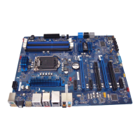
Intel Desktop Board DZ77BH-55K Technical Product Specification
14
Table 3. Components Shown in Figure 1
Label Description
A PCI Express x1 bus add-in card connector
B Conventional PCI bus add-in card connector
C PCI Express x16 bus add-in card connector (x8 electrical; x16 compatible)
D Front panel audio header
E Conventional PCI bus add-in card connector
F PCI Express x1 bus add-in card connector
G PCI Express x16 bus add-in card connector
H Battery
I PCI Express x1 bus add-in card connector
J Rear chassis fan header
K Back panel connectors
L 12 V processor core voltage connector (2 x 4 pin)
M LGA1155 processor socket
N VR status LEDs
O Processor fan header
P DIMM 3 (Channel A DIMM 0)
Q DIMM 1 (Channel A DIMM 1)
R DIMM 4 (Channel B DIMM 0)
S DIMM 2 (Channel B DIMM 1)
T Front chassis fan header
U Piezoelectric speaker
V Main power connector (2 x 12)
W LED2 (Power Fault)
X Onboard power button
Y Standby power LED
Z SATA 3.0 Gb/s connector through the PCH (black)
AA Intel Z77 Express Chipset
BB SATA 6.0 Gb/s connector through the PCH (blue)
CC SATA 3.0 Gb/s connector through the PCH (black)
DD SATA 6.0 Gb/s connector through a Marvel 88SE9172 controller (gray)
EE Alternate front panel power LED header
FF Front panel header
GG Power On Self Test (POST) code LED display
HH Front panel USB 2.0 connectors
II Chassis intrusion header
JJ Consumer IR receiver (input) header
KK Front panel USB 3.0 connector (blue)
LL Consumer IR transmitter (output) header
continued

 Loading...