Product Description
43
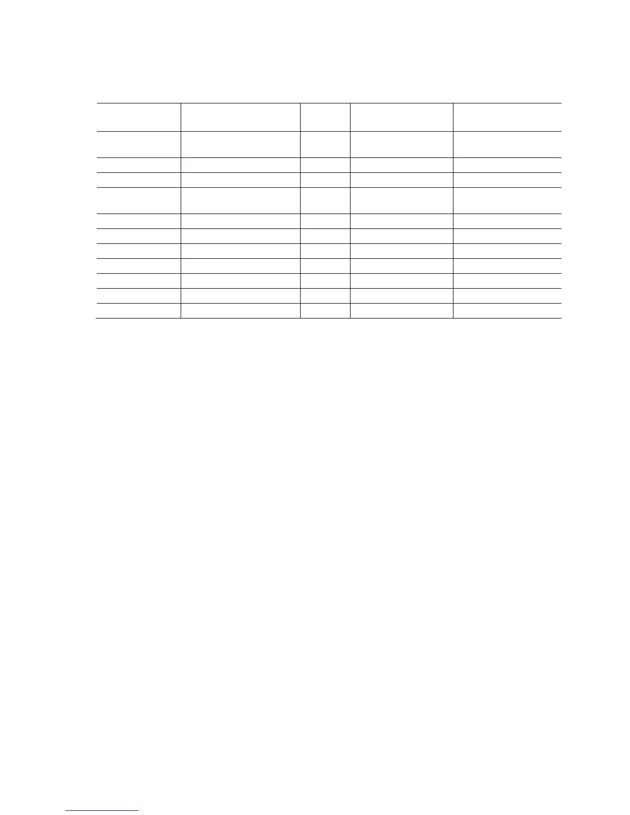
Table 13. Board Status LEDs
Item/Callout
in Figure 9
LED Name
LED
Color
Supported Modes
Control Source
A Hard Drive Activity Blue On/Off Hard drive
controller(s)
B CPU Hot Red On/Off Discrete circuit
C VR Hot Red On/Off Discrete circuit
D Watch Dog Fire / Back to
BIOS
Red On/Off/Flash BIOS
E CPU Initialization Green On/Off/Flash BIOS
F Memory Initialization Green On/Off/Flash BIOS
G Video Initialization Green On/Off/Flash BIOS
H USB Initialization Green On/Off/Flash BIOS
I Hard Drive Initialization Green On/Off/Flash BIOS
J Option ROM Initialization Green On/Off/Flash BIOS
K Operating System Start Green On/Off/Flash BIOS