Reference Thermal Solutions
R
30 Intel
®
E7500/E7505 Chipset MCH Thermal Design Guide
6.4 Reliability Guidelines
Each motherboard, heatsink and attach combination may vary the mechanical loading of the
component. Based on the end user environment, the user should define the appropriate reliability
test criteria and carefully evaluate the completed assembly prior to use in high volume. Some
general recommendations are shown in Table 3.
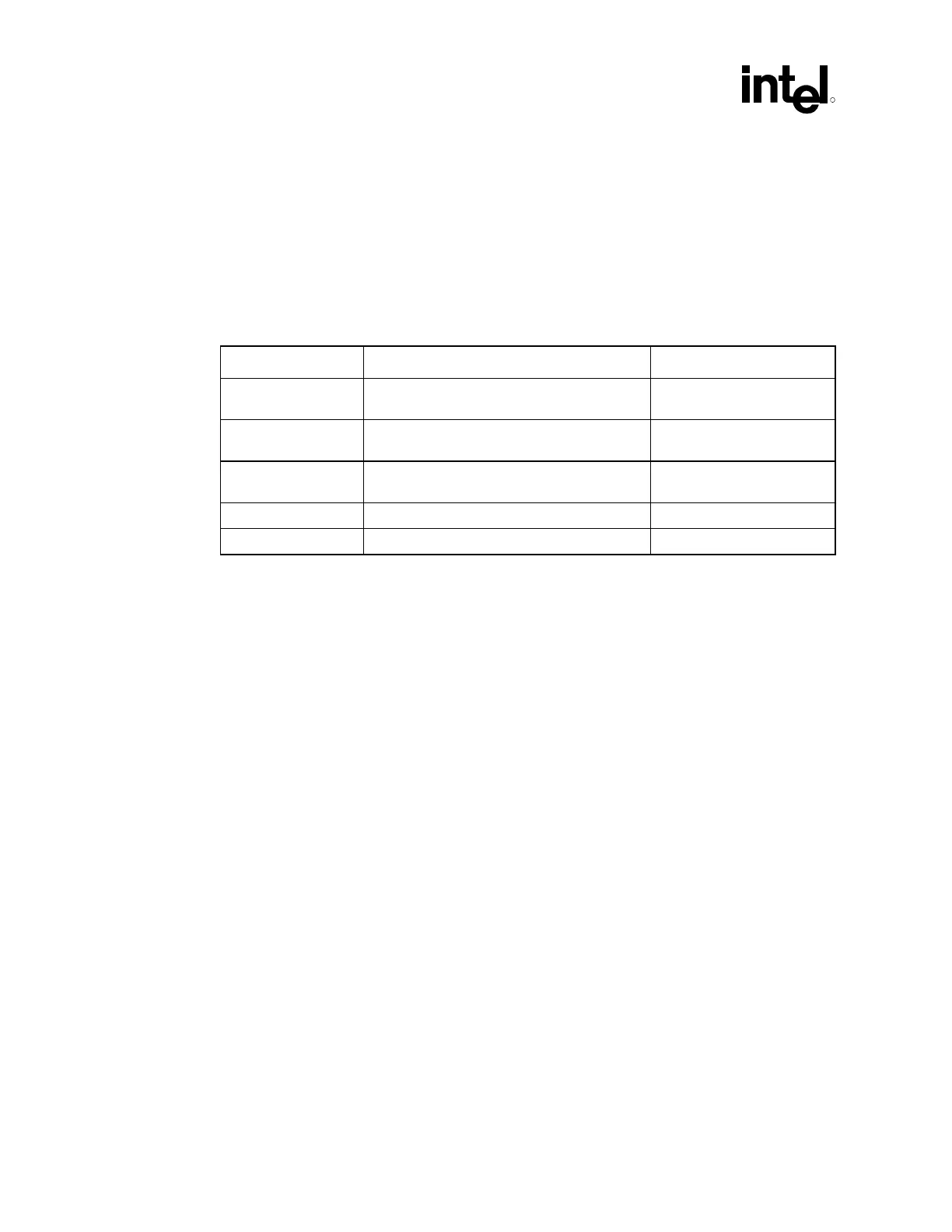
Table 3. Reliability Guidelines
Test Test Profile Pass/Fail Criteria
Mechanical Shock 50 g, board level, 11 msec, 3 shocks/axis Visual Check and Electrical
Functional Test
Random Vibration 7.3 g, board level, 45 min/axis, 50 Hz to
2000 Hz
Visual Check and Electrical
Functional Test
Temperature Life 85 °C, 2000 hours total, checkpoints at 168,
500, 1000, and 2000 hours
Visual Check
Thermal Cycling -5 °C to +70 °C, 500 cycles Visual Check
Humidity 85% relative humidity, 55 °C, 1000 hours Visual Check
NOTES:
1. It is recommended that the above tests are performed on a sample size of at least 12
assemblies from 3 lots of material.
2. Additional Pass/Fail Criteria may be added at the discretion of the user.