Reference Thermal Solutions
R
Intel
®
E7500/E7505 Chipset MCH Thermal Design Guide 23
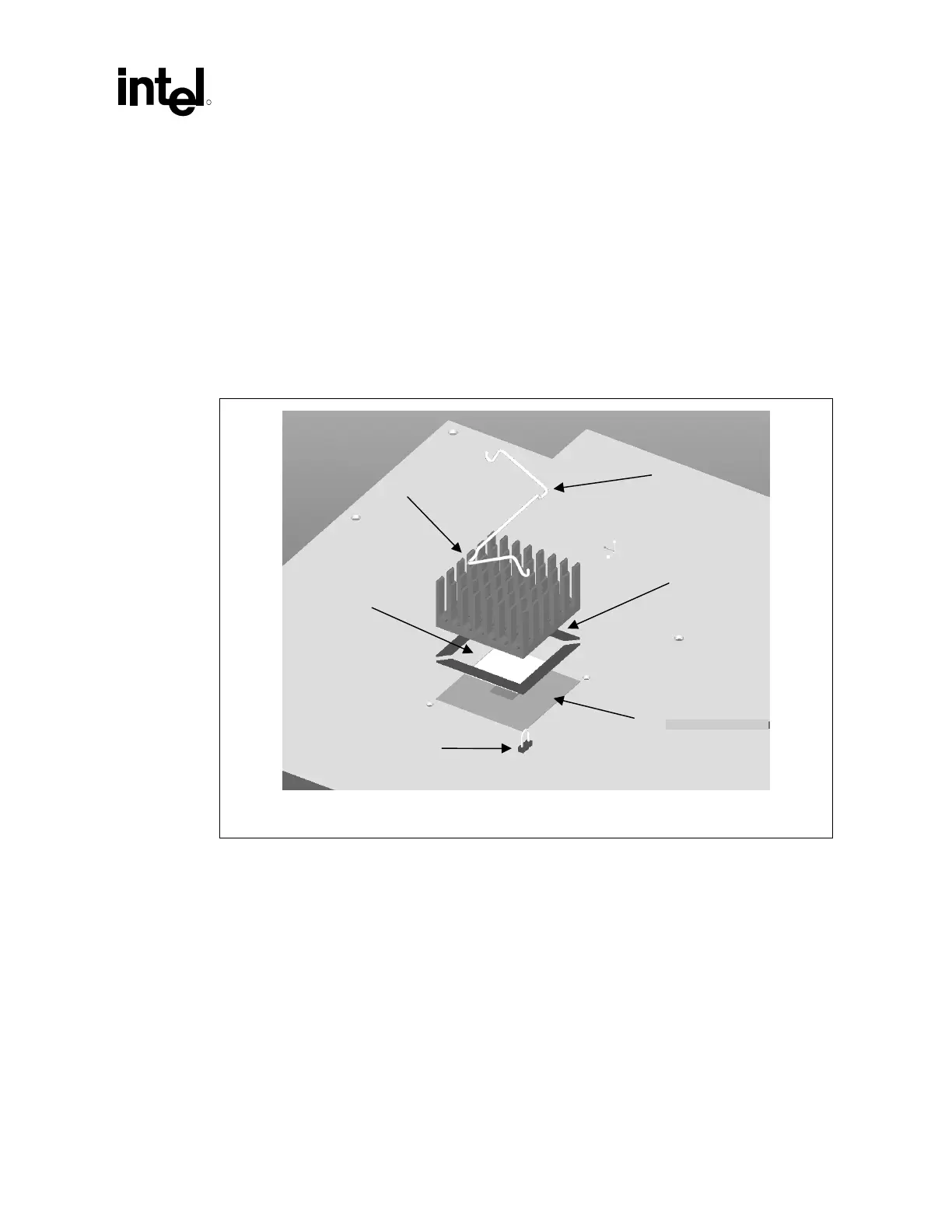
6.3 Thermal Solution Assembly
The reference thermal solution is a passive extruded heatsink with thermal and mechanical
interfaces. It is attached using a clip with each end hooked through an anchor soldered to the
board. Figure 8 shows the reference thermal solution assembly and associated components.
Figure 9 and Figure 10 show alternate views of the reference solution. Full mechanical drawings of
the thermal solution assembly and the heatsink clip are provided in Appendix B. Appendix A
contains vendor information for each thermal solution component.
Figure 8. Reference Thermal Solution Assembly
FC-BGA
Mechanical
nchored
Solde
-Down
Thermal
Heatsin
ref_therm_solution_assy